¶ Argon Industria HMI Assembly Guide
¶ Overview
The Argon Industria HMI is an industrial-grade Human-Machine Interface enclosure system designed for the Raspberry Pi 5. It is purpose-built for makers, developers, and system integrators who need a reliable, compact, and professional-looking panel computer for automation, monitoring, and embedded display applications. The Industria HMI is available in four display configurations — 5", 7", 8", and 10" — as well as a Case Only variant for users who wish to supply their own display. Each configuration includes an integrated NVMe expansion board for high-speed storage and a passive cooling column for silent, fanless thermal management.
¶ Compatible Devices
| Component | Compatible Models |
|---|---|
| Single-Board Computer | Raspberry Pi 5 (4 GB / 8 GB) |
| M.2 NVMe SSD | M.2 2230 / 2242 (PCIe Gen 2 / Gen 3, NVMe only) |
| Display (5" / 7" SKU) | Argon 5" Touch Display, Argon 7" Touch Display |
| Display (8" / 10" SKU) | Argon 8" Touch Display, Argon 10" Touch Display |
| Operating System | Raspberry Pi OS (Bookworm or later), Ubuntu 24.04 for RPi |
⚠️ Warning: SATA M.2 drives are not supported. Only PCIe NVMe M.2 drives are compatible with the Argon HMI NVMe Board.
📝 Note: The Raspberry Pi 4 is not compatible with the Argon Industria HMI system. The board connectors and PCIe interface are designed exclusively for the Raspberry Pi 5.
¶ What's in the Box
¶ 5" & 7" SKU
| Item | Qty |
|---|---|
| Argon Industria HMI Body (Main Case) | 1 |
| Argon Industria HMI Display Case | 1 |
| Argon HMI-HDMI Board | 1 |
| Argon HMI NVMe Board | 1 |
| Argon 5" or 7" Touch Display | 1 |
| Passive Cooling Column (Heatsink) | 1 |
| Silicon Thermal Pad | 1 |
| PCIe Flat Flex Cable | 1 |
| HMI-Display Flat Flex Cable | 1 |
| Power Supply Cable (3-pin GPIO to 2-pin Display) | 1 |
| Display Case Bracket | 1 |
| Flat Head Screws (Board Mounting) | Set |
| Silver Flat Head Screws (Enclosure Assembly) | Set |
| Standoffs | Set |
| NVMe Screw | 1 |
¶ 8" & 10" SKU
| Item | Qty |
|---|---|
| Argon Industria HMI Body (Main Case) | 1 |
| Argon Industria HMI Display Case | 1 |
| Argon HMI-HDMI Board | 1 |
| Argon HMI NVMe Board | 1 |
| Argon 8" or 10" Touch Display | 1 |
| Passive Cooling Column (Heatsink) | 1 |
| Silicon Thermal Pad | 1 |
| PCIe Flat Flex Cable | 1 |
| HMI-HDMI Flat Flex Cable | 1 |
| Power Supply Cable (3-pin GPIO to 2-pin Display) | 1 |
| Display Case Bracket | 1 |
| Flat Head Screws (Board Mounting) | Set |
| Silver Flat Head Screws (Enclosure Assembly) | Set |
| Standoffs | Set |
| NVMe Screw | 1 |
¶ Case Only SKU
| Item | Qty |
|---|---|
| Argon Industria HMI Body (Main Case) | 1 |
| Argon Industria HMI Cover | 1 |
| Argon HMI-HDMI Board | 1 |
| Argon HMI NVMe Board | 1 |
| Passive Cooling Column (Heatsink) | 1 |
| Silicon Thermal Pad | 1 |
| PCIe Flat Flex Cable | 1 |
| Flat Head Screws (Board Mounting) | Set |
| Silver Flat Head Screws (Enclosure Assembly) | Set |
| Standoffs | Set |
| NVMe Screw | 1 |
📝 Note: The M.2 NVMe SSD and Raspberry Pi 5 are not included in any SKU and must be sourced separately.
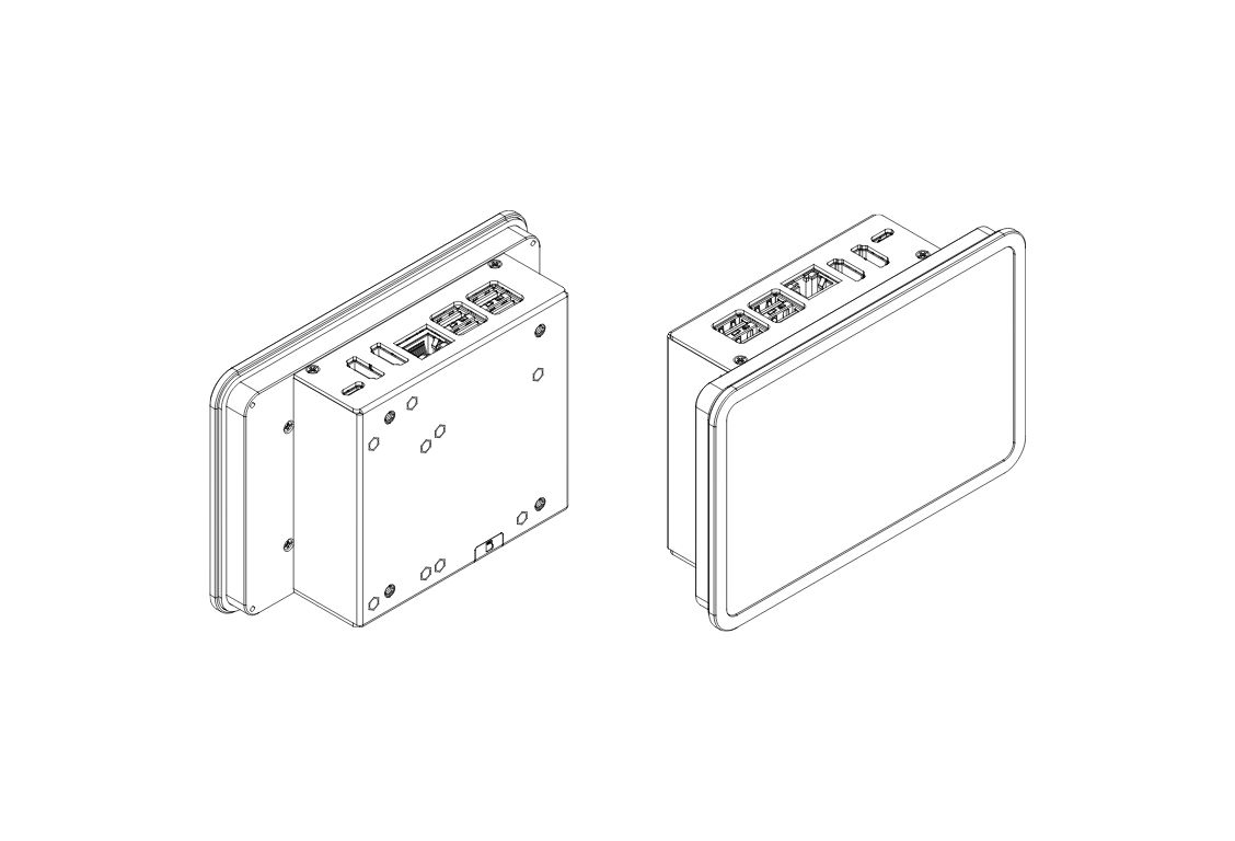
¶ 5" & 7" Parts and Features
¶ Argon Industria HMI 5" / 7"
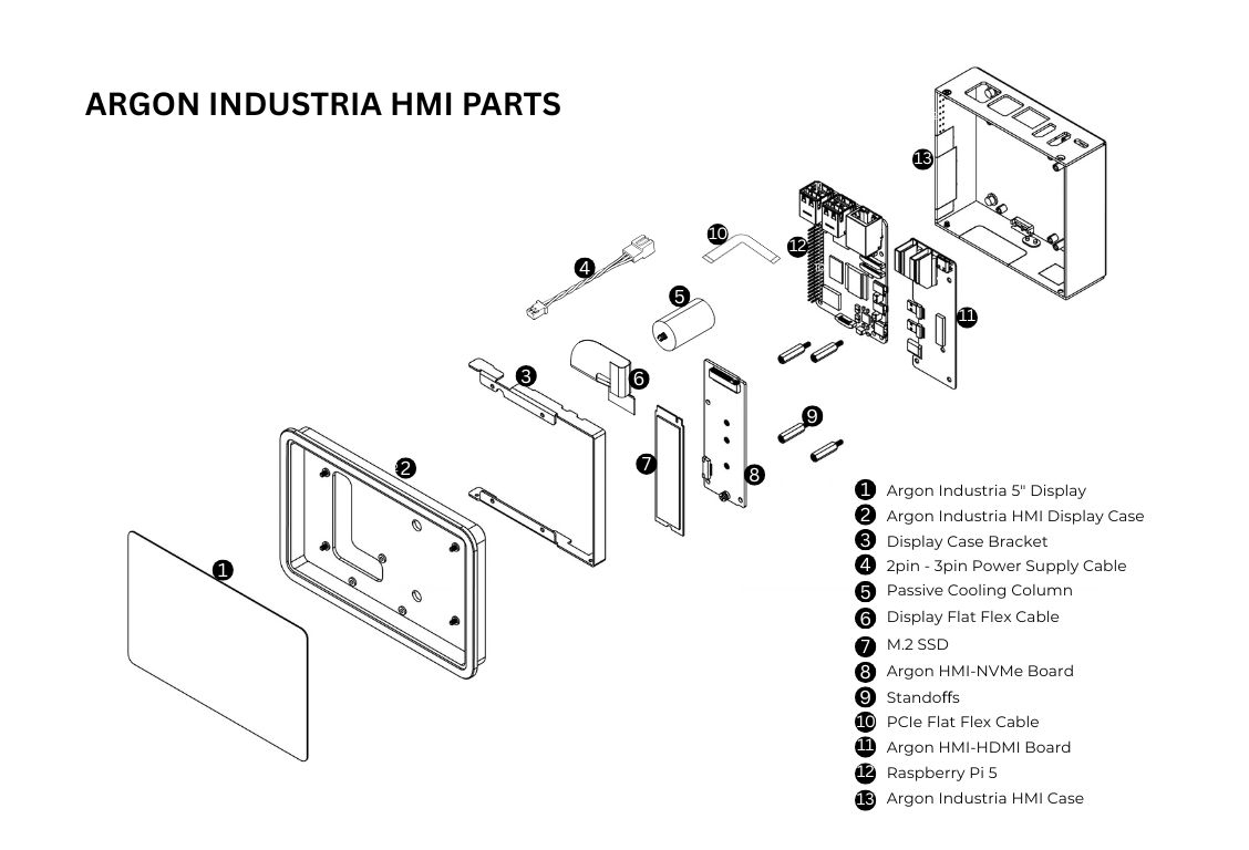
¶ 5" & 7" Assembly & Setup
⚠️ Warning: Before beginning assembly, ensure the Raspberry Pi 5 is powered off and disconnected from any power source. Assembling under power may permanently damage the boards.
📝 Note: Handle all Flat Flex Cables (FFC) gently. Creasing or tearing an FFC will require replacement of the cable before the unit can function.
Step 1 — Apply the Thermal Pad to the Raspberry Pi 5
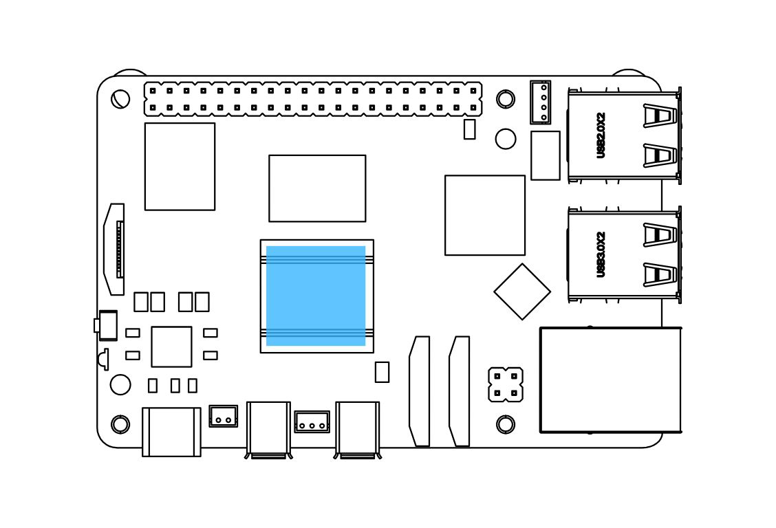
Apply the Silicon Thermal Pad on the top of the Raspberry Pi 5 SoC. Make sure to REMOVE THE TRANSPARENT BACKING on both sides of the thermal pad before placing it. The pad must make direct contact with the SoC on one side and the passive cooling column on the other.
Step 2 — Connect the Raspberry Pi 5 to the Argon HMI-HDMI Board
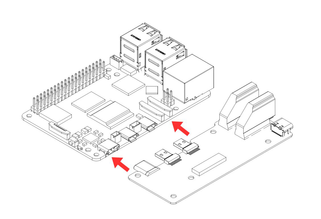
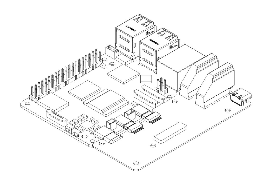
Slide the Raspberry Pi 5 into the Argon HMI-HDMI Board connector. PUSH ALL THE WAY IN. The HDMI-Power Daughterboard must be FULLY SEATED into the RPi 5 GPIO and USB-C connectors to AVOID POWER-UP ISSUES.
⚠️ Warning: A partially connected HMI-HDMI Board is one of the most common causes of a no-power or no-display fault. Verify the connection is flush and fully engaged before proceeding.
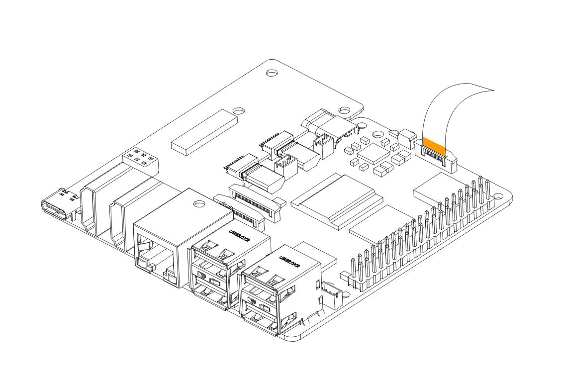
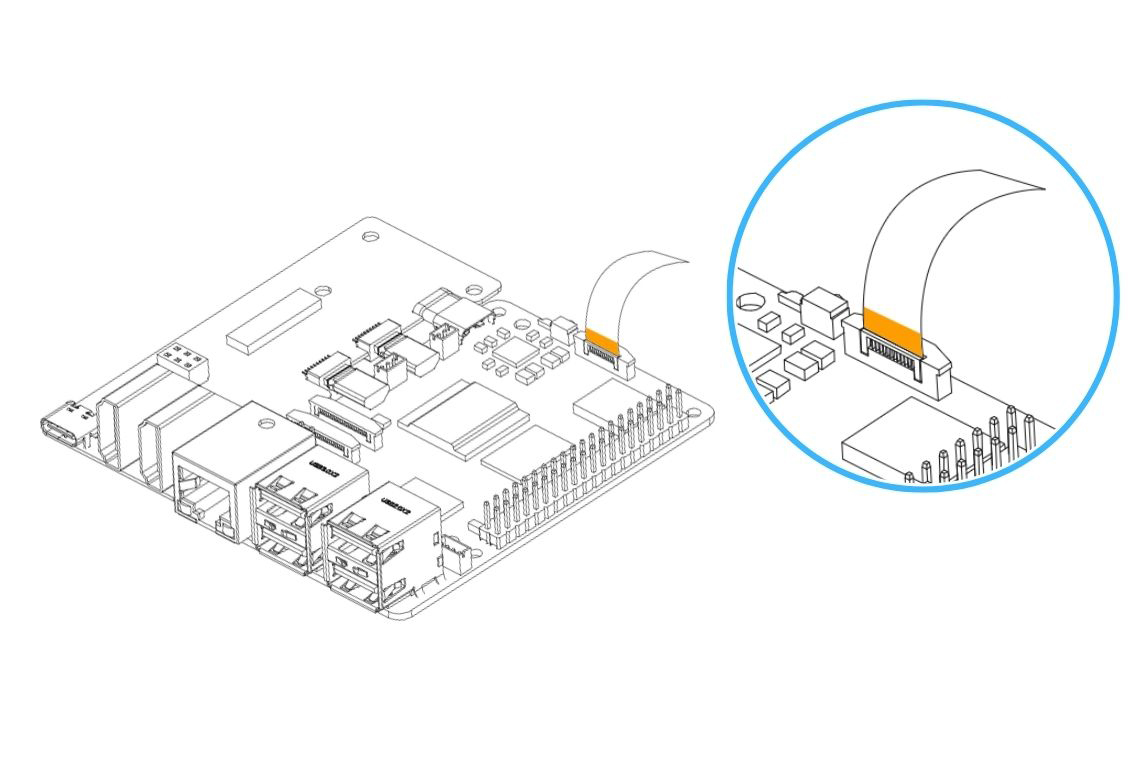
Step 3 — Connect the PCIe Flat Flex Cable to the Raspberry Pi 5
Carefully connect the PCIe Flat Flex Cable to the PCIe connector on the Raspberry Pi 5.
- Gently pull up the brown flip-lock cover on the RPi 5 PCIe connector to release the lock.
- Insert the cable with the COPPER CONTACTS FACING the white back side of the PCIe connector.
- Press the brown flip-lock back down firmly to secure the cable.
⚠️ Warning: Do not force the flip-lock. If it resists, the cable is likely not fully seated. Remove the cable, realign, and reinsert before closing the lock.
Step 4 — Mount the Boards into the Argon Industria HMI Case
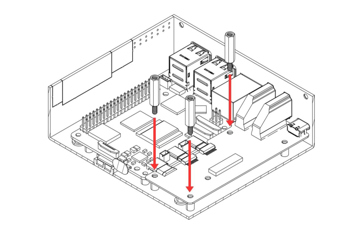
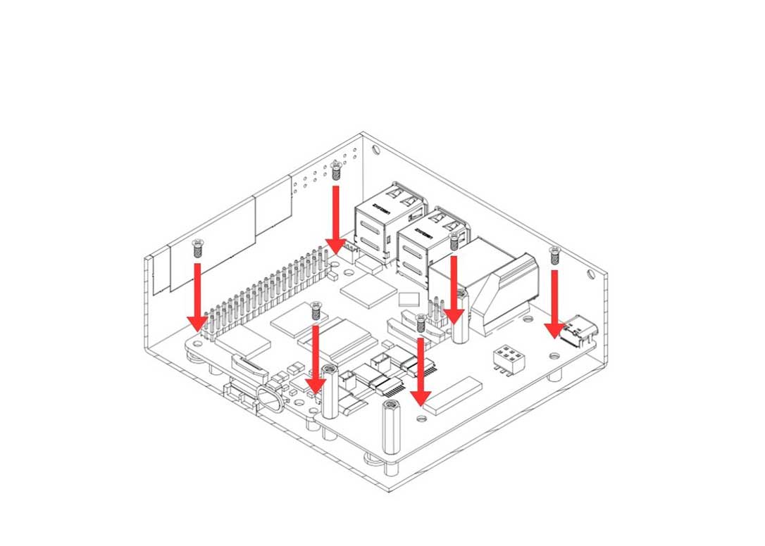
Carefully lower the Raspberry Pi 5 and the Argon HMI-HDMI Board assembly into the Argon Industria HMI Body. Align the mounting holes and:
- Secure the Raspberry Pi 5 to the case using the flat head screws.
- Secure the Argon HMI-HDMI Board using the standoffs — these standoffs will also serve as the mounting points for the NVMe Board in the next step.
Step 5 — Connect the Display Flat Flex Cable to the Raspberry Pi 5
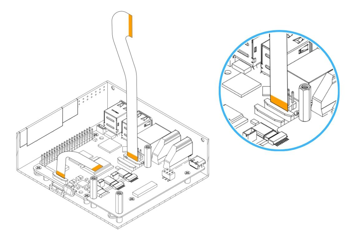
Carefully connect the HMI-Display Flat Flex Cable to the display connector on the Raspberry Pi 5.
- Gently pull the flip-lock cover on the display connector to release the lock.
- Insert the cable fully.
- Press the flip-lock back down firmly to secure the cable.
Step 6 — Attach the Argon HMI NVMe Board
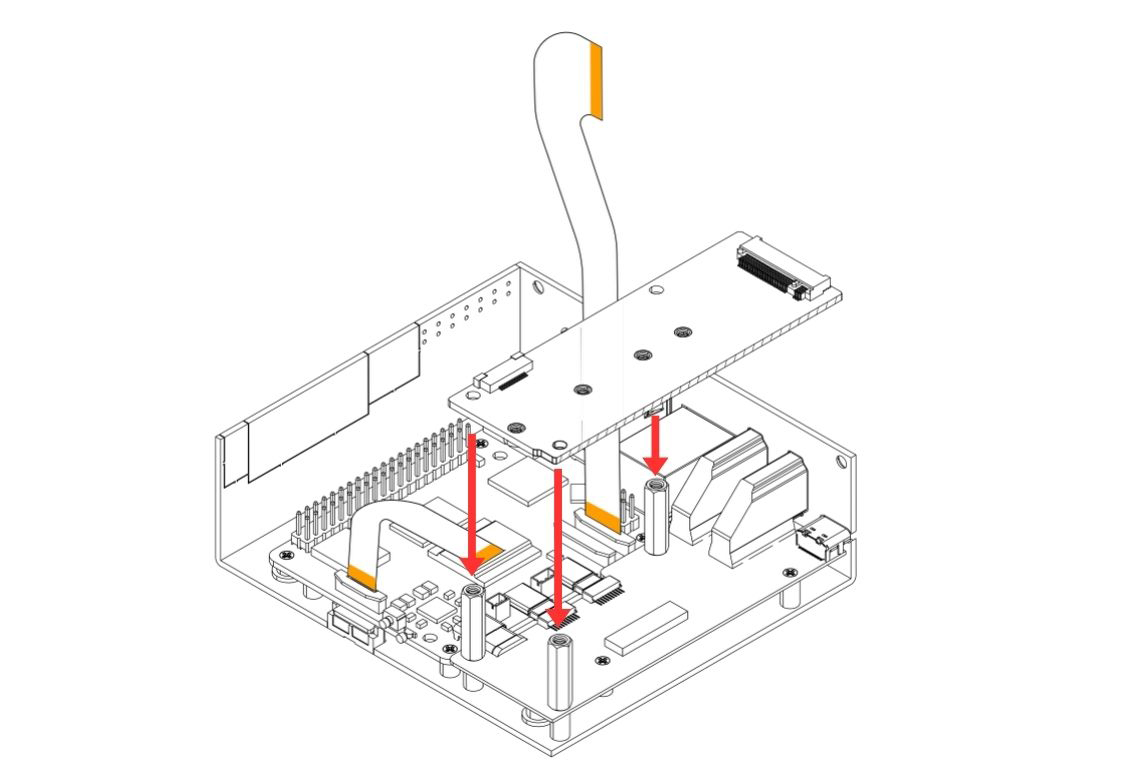
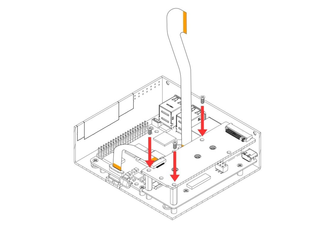
Carefully lower the Argon HMI NVMe Board on top of the Argon HMI-HDMI Board. Align the NVMe Board mounting holes to the standoffs installed in Step 4 and secure using the flat head screws.
Step 7 — Install the M.2 NVMe SSD
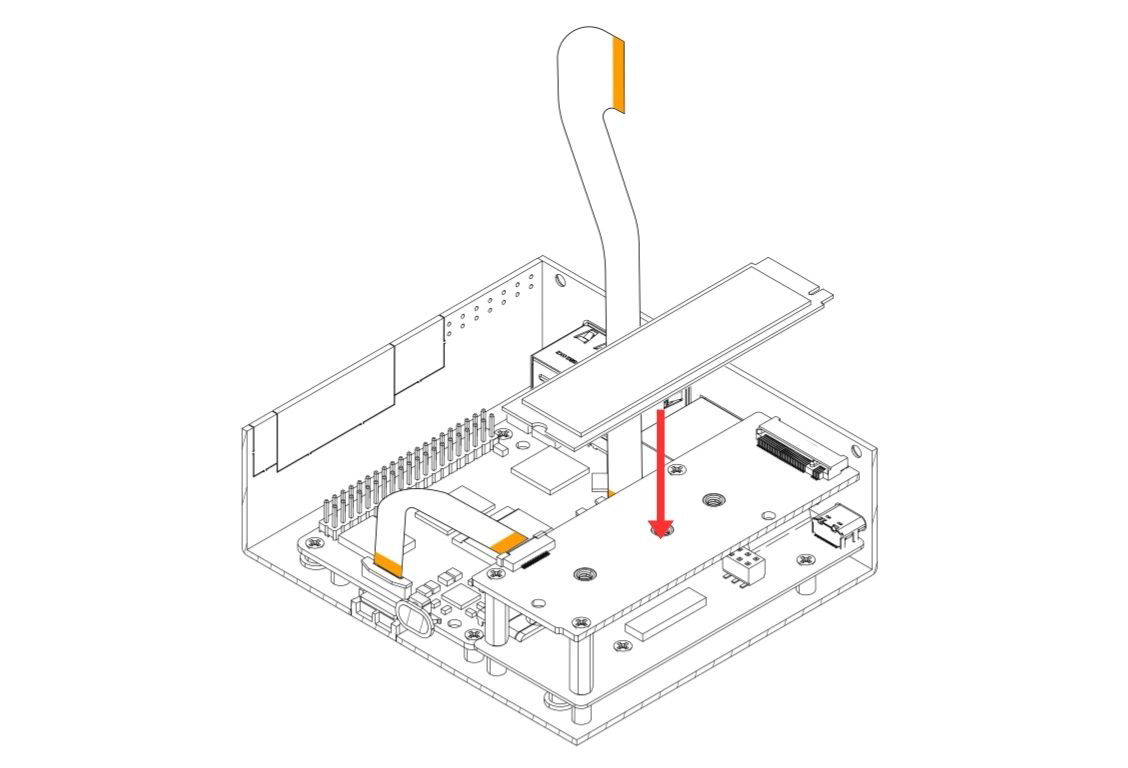
Insert the M.2 NVMe SSD into the M.2 slot on the Argon HMI NVMe Board at an angle, then press the drive down flat and secure it using the NVMe screw.
📝 Note: Only PCIe NVMe M.2 drives in 2230 or 2242 form factors are supported. SATA M.2 drives will not function.
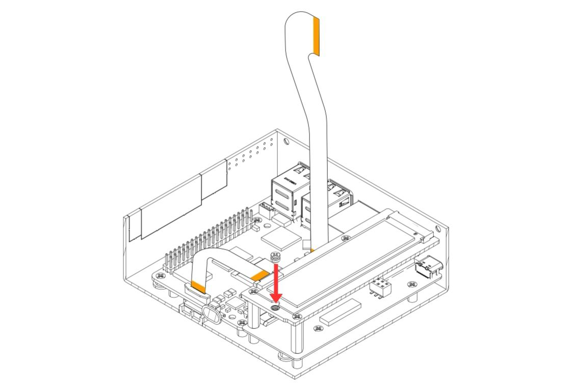
Step 8 — Connect the PCIe Flat Flex Cable to the Argon NVMe Board
Carefully connect the other end of the PCIe Flat Flex Cable (installed at the RPi 5 end in Step 3) to the PCIe connector on the Argon NVMe Board.
- Gently pull the flip-lock cover on the NVMe Board PCIe connector to release the lock.
- Insert the cable fully.
- Press the flip-lock back down firmly to secure the cable.
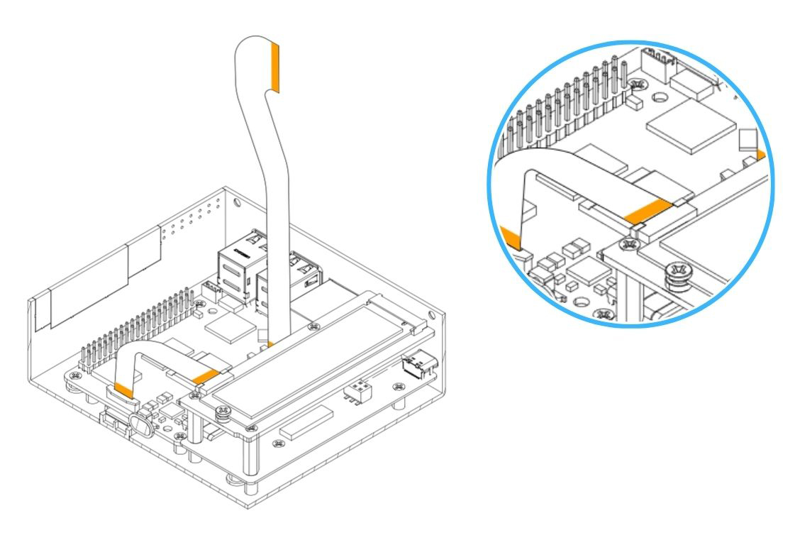
Step 9 — Attach the Passive Cooling Column and Touch Display to the Display Case
- Attach the Passive Cooling Column to the Display Case and secure using the flat head screws.
- Place the Raspberry Pi 5" / 7" Touch Display into the Display Case.
- Secure the Touch Display using the flat head screws.
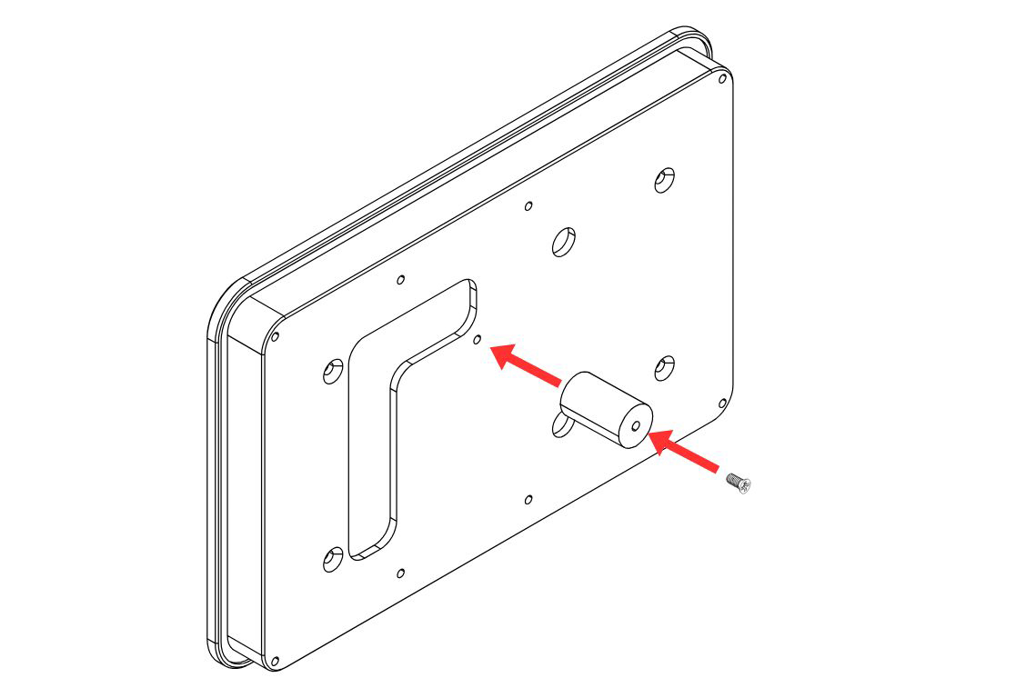
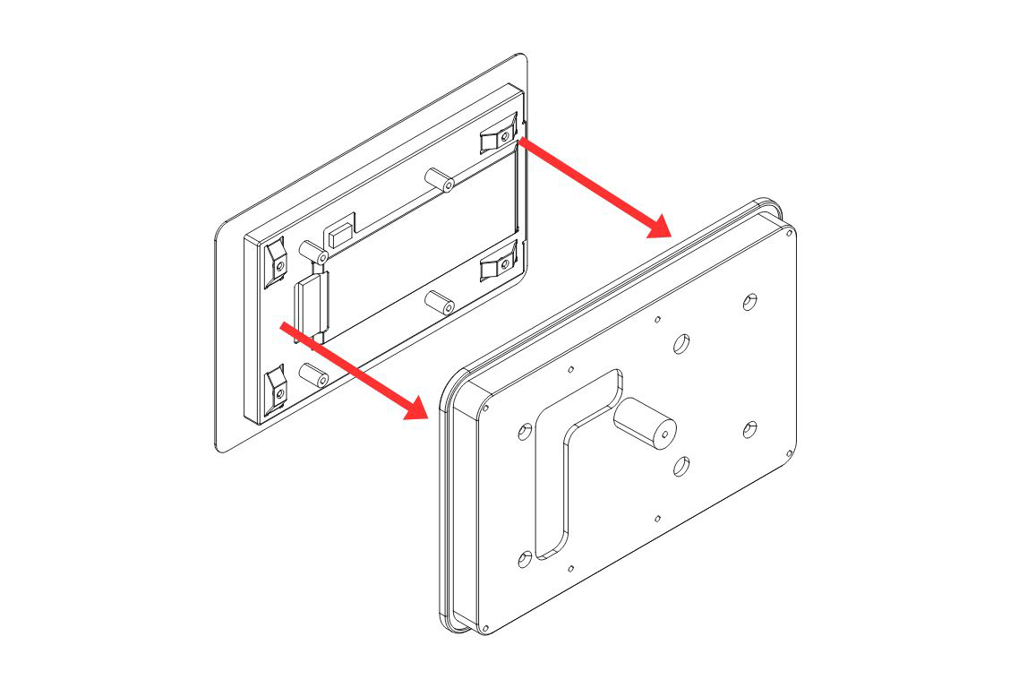
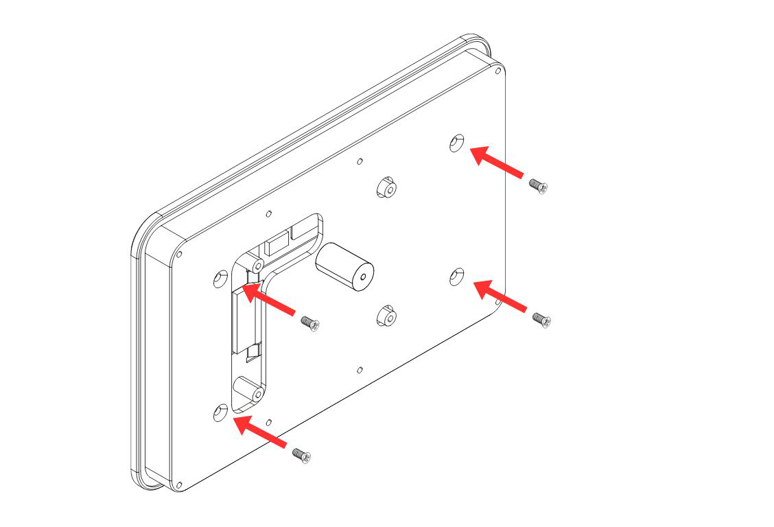
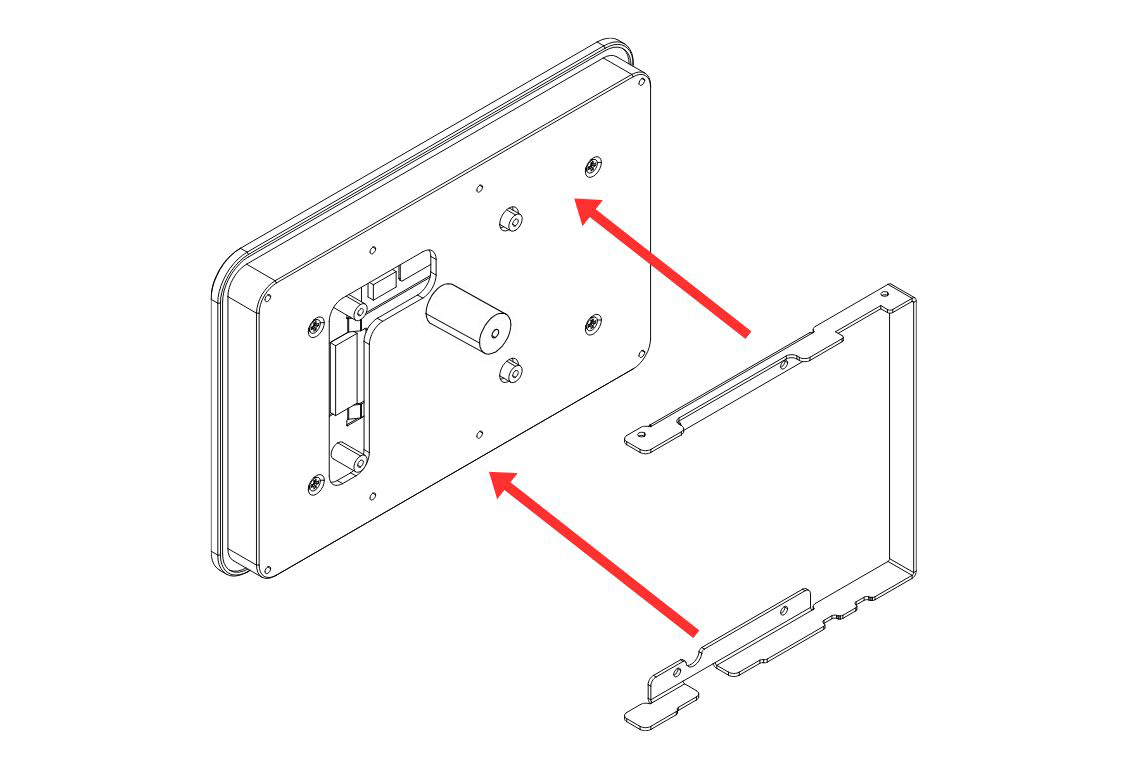
Step 10 — Attach the Bracket to the Display Case
Attach the Display Case Bracket to the Display Case and secure using the flat head screws.
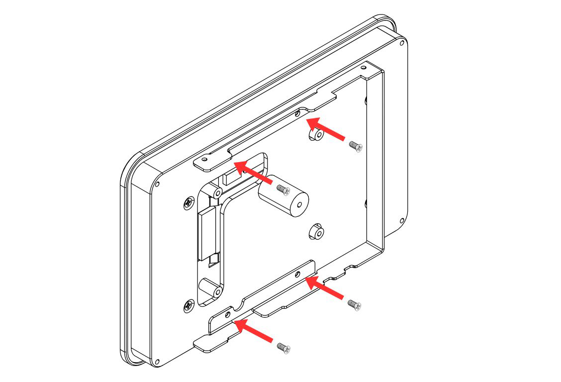
Step 11 — Connect the Display Flat Flex Cable to the Touch Display
Carefully connect the HMI-Display Flat Flex Cable to the connector on the Argon Touch Display.
- Gently pull the flip-lock cover on the display connector to release the lock.
- Insert the cable fully.
- Press the flip-lock back down firmly to secure the cable.
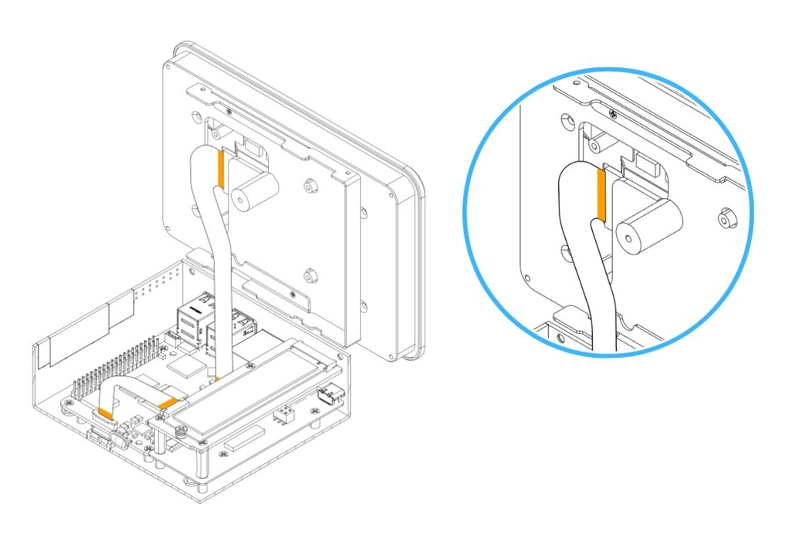
Step 12 — Connect the Power Supply Cable to the GPIO
Carefully connect the 3-pin end of the Power Supply Cable to the Raspberry Pi 5 GPIO header. Ensure the cable is aligned to the correct pins:
| GPIO Pin | Function |
|---|---|
| Pin 2 | 5V Power |
| Pin 4 | 5V Power |
| Pin 6 | Ground (GND) |
⚠️ Warning: Connecting the power cable to the wrong GPIO pins can permanently damage the Raspberry Pi 5 or the Touch Display. Double-check pin alignment before powering on.
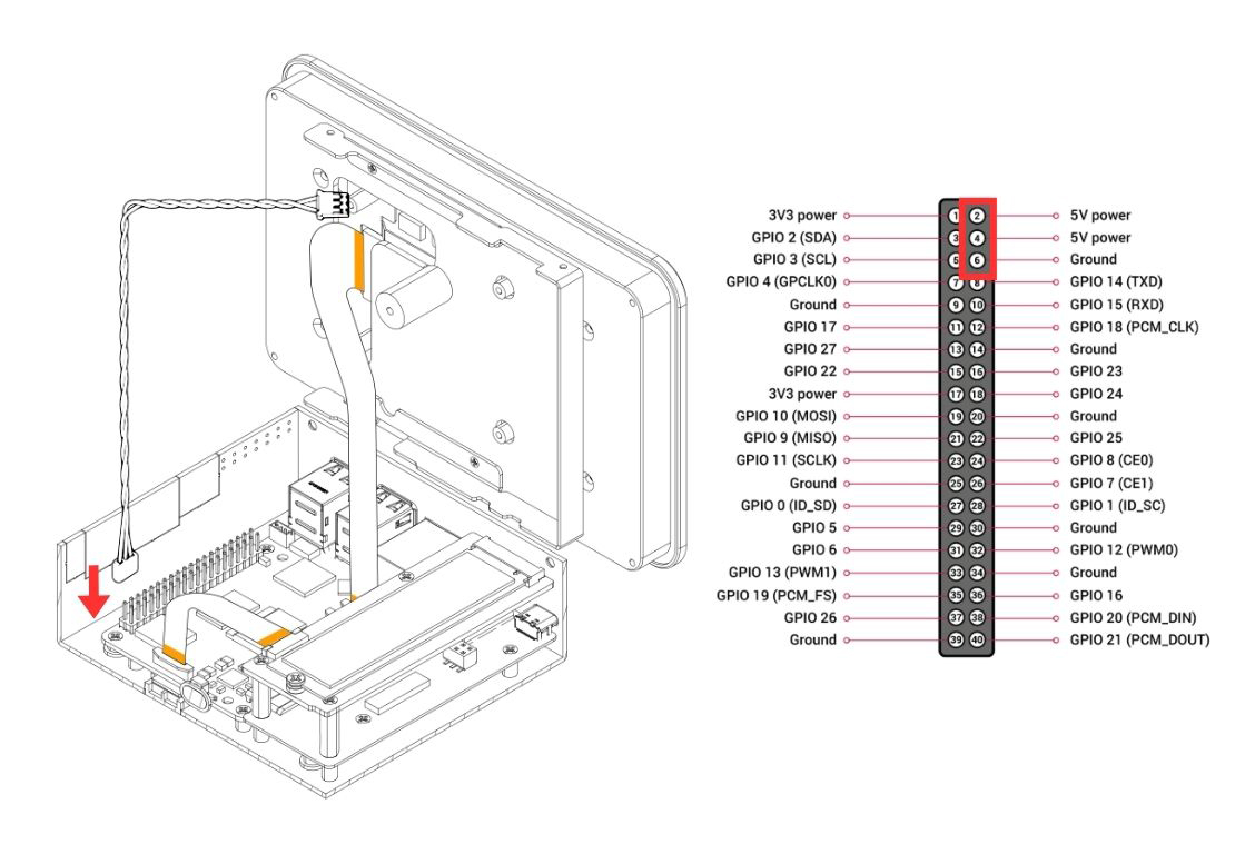
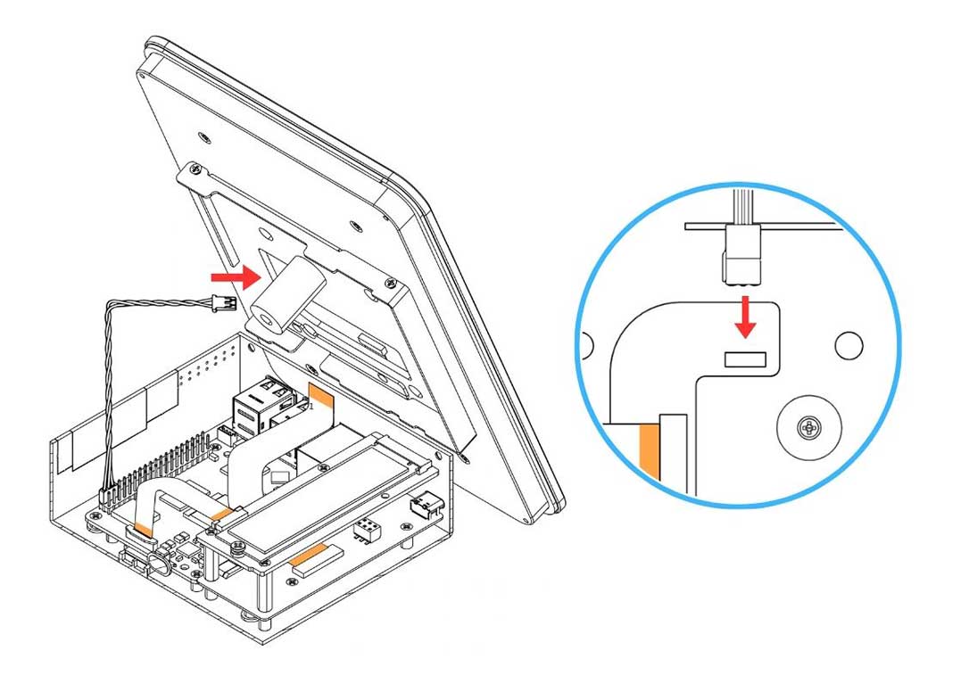
Step 13 — Connect the Power Supply Cable to the Argon Touch Display
Carefully connect the 2-pin end of the Power Supply Cable to the power connector on the Argon Touch Display. Make sure the connector is fully and correctly seated.
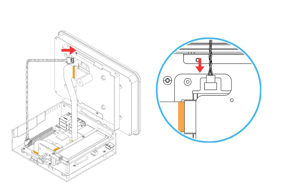
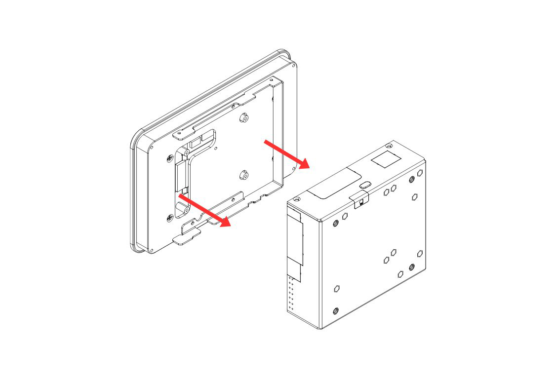
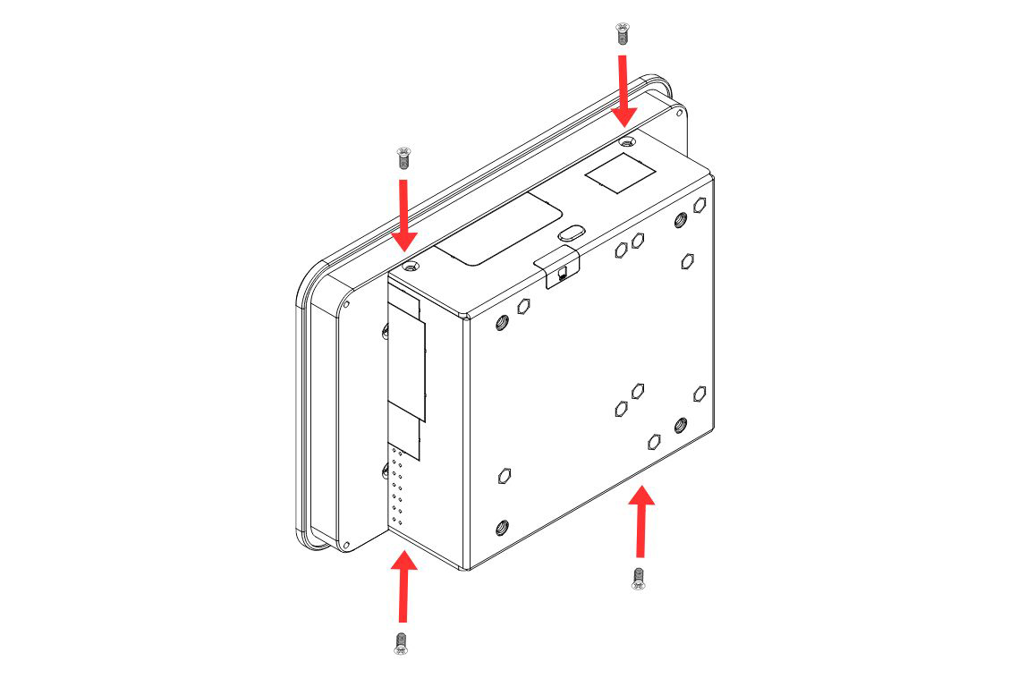
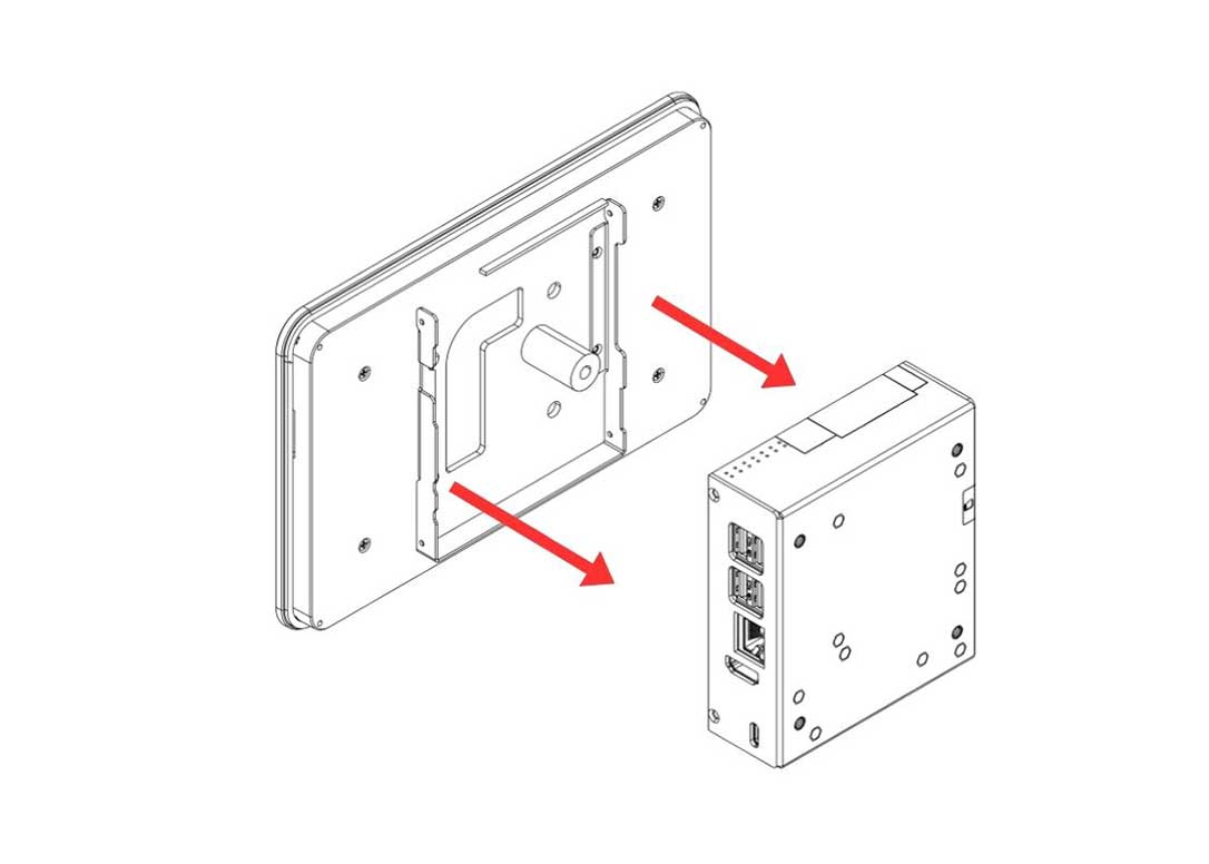
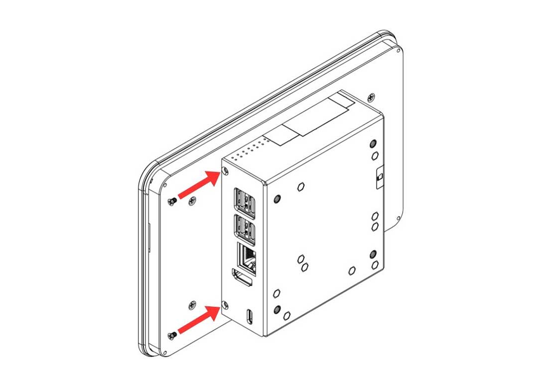
Step 14 — Attach the HMI Display Assembly to the Body
Carefully bring the Display Case assembly to the HMI Body and align the mounting points. Secure the Display Case to the Body using the silver flat head screws.
¶ 8" & 10" Parts and Features
¶ Argon Industria HMI 8" / 10"
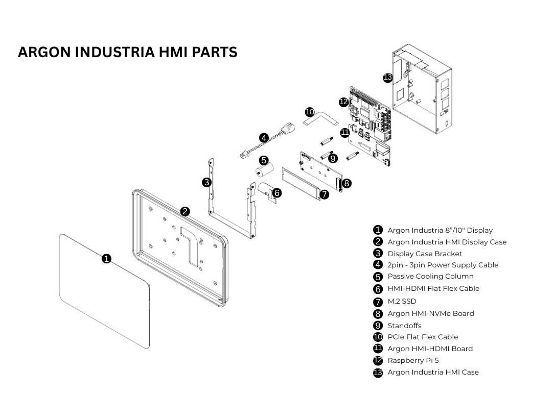
¶ 8" & 10" Assembly & Setup
⚠️ Warning: Before beginning assembly, ensure the Raspberry Pi 5 is powered off and disconnected from any power source. Assembling under power may permanently damage the boards.
📝 Note: The 8" and 10" assembly uses an HMI-HDMI Flat Flex Cable to route the video signal to the display — this is a different cable routing method from the 5" / 7" SKUs. Pay close attention to the no.1 and no.2 end labelling on the cable at Steps 5 and 11.
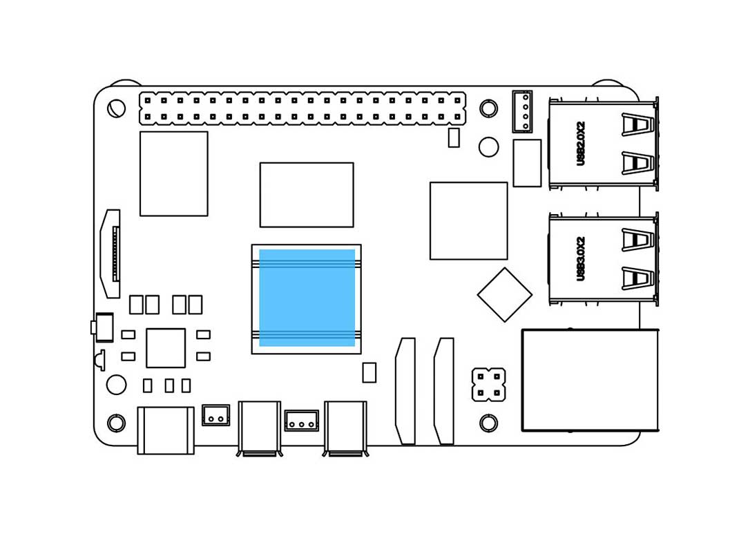
Step 1 — Apply the Thermal Pad to the Raspberry Pi 5
Apply the Silicon Thermal Pad on the top of the Raspberry Pi 5 SoC. Make sure to REMOVE THE TRANSPARENT BACKING on both sides of the thermal pad before placing it.
Step 2 — Connect the Raspberry Pi 5 to the Argon HMI-HDMI Board
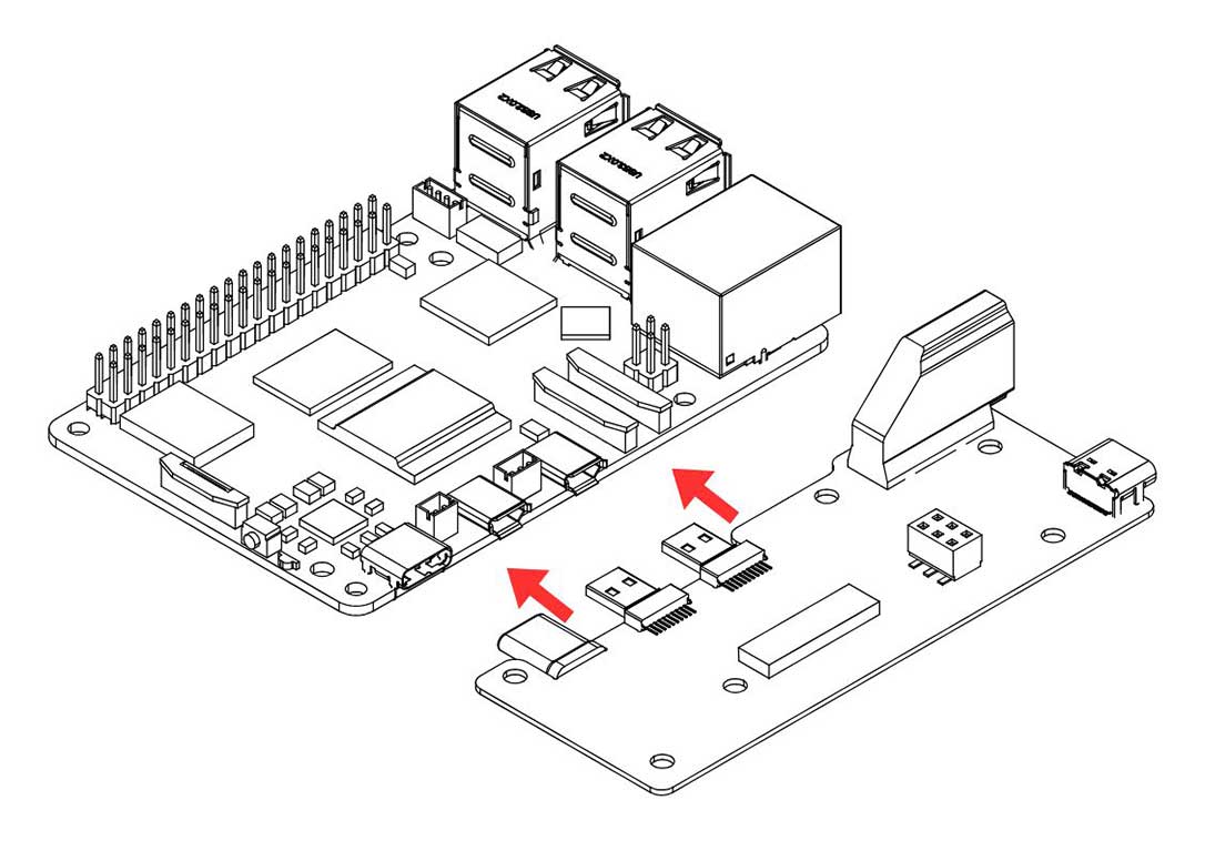
Slide the Raspberry Pi 5 into the Argon HMI-HDMI Board connector. PUSH ALL THE WAY IN. The HDMI-Power Daughterboard must be FULLY SEATED into the RPi 5 GPIO and USB-C connectors to AVOID POWER-UP ISSUES.
⚠️ Warning: A partially connected HMI-HDMI Board is one of the most common causes of a no-power or no-display fault. Verify the connection is flush and fully engaged before proceeding.
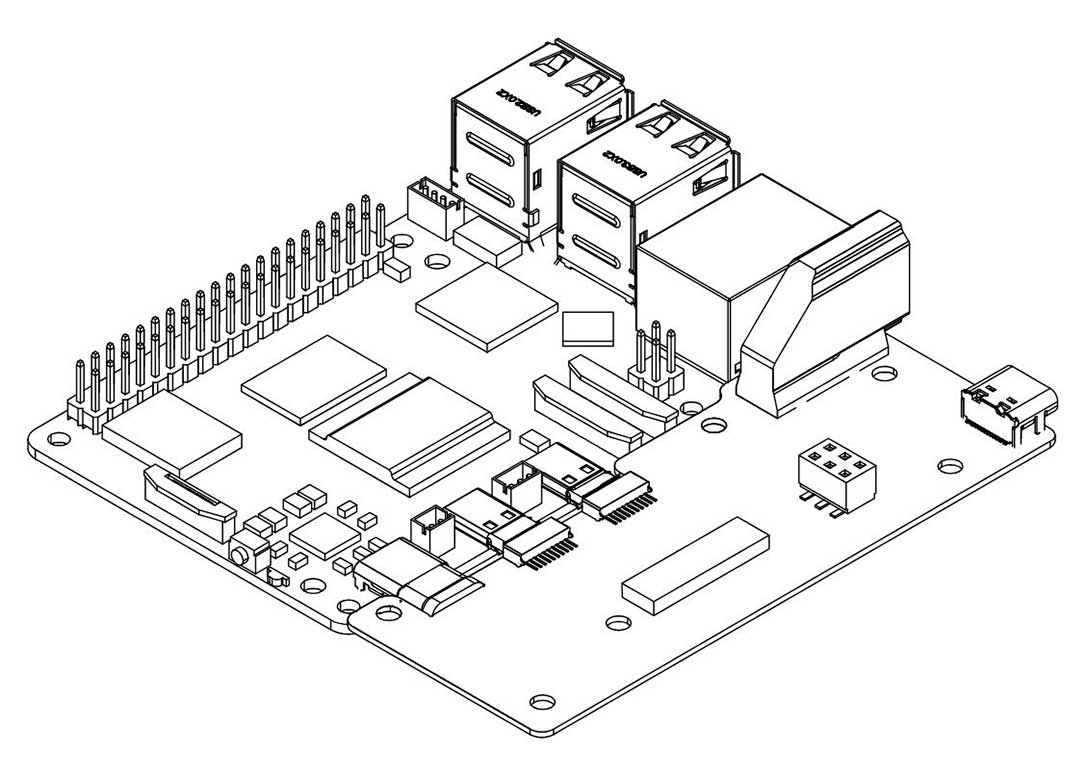
Step 3 — Connect the PCIe Flat Flex Cable to the Raspberry Pi 5
Carefully connect the PCIe Flat Flex Cable to the PCIe connector on the Raspberry Pi 5.
- Gently pull up the brown flip-lock cover on the RPi 5 PCIe connector to release the lock.
- Insert the cable with the COPPER CONTACTS FACING the white back side of the PCIe connector.
- Press the brown flip-lock back down firmly to secure the cable.
⚠️ Warning: Do not force the flip-lock. If it resists, the cable is not fully seated. Remove, realign, and reinsert before closing the lock.
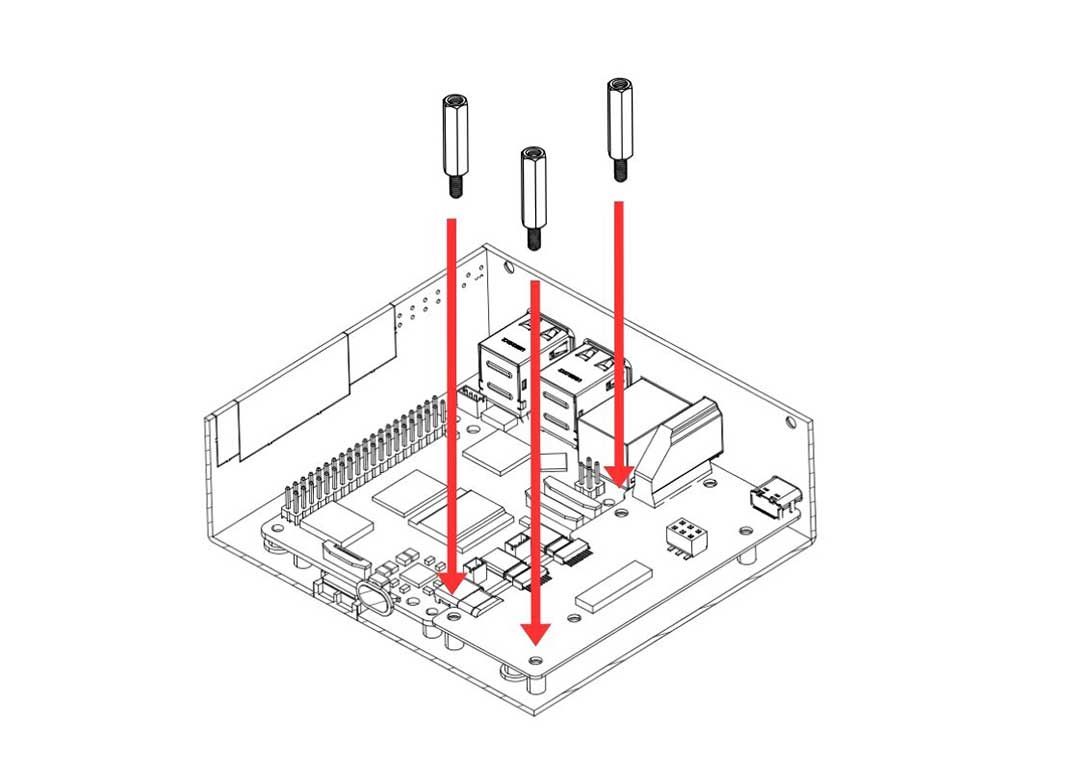
Step 4 — Mount the Boards into the Argon Industria HMI Case
Carefully lower the Raspberry Pi 5 and the Argon HMI-HDMI Board assembly into the Argon Industria HMI Body. Align the mounting holes and:
- Secure the Argon HMI-HDMI Board using the standoffs — these will serve as mounting points for the NVMe Board later.
- Secure the Raspberry Pi 5 to the case using the flat head screws.
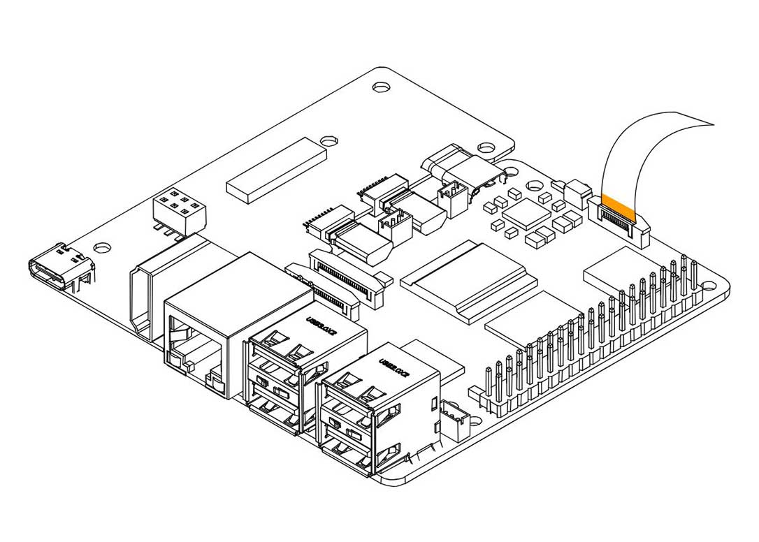
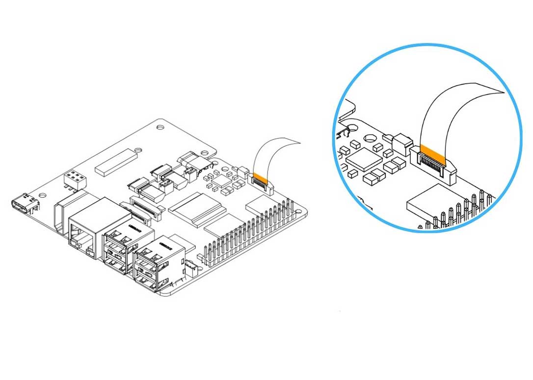
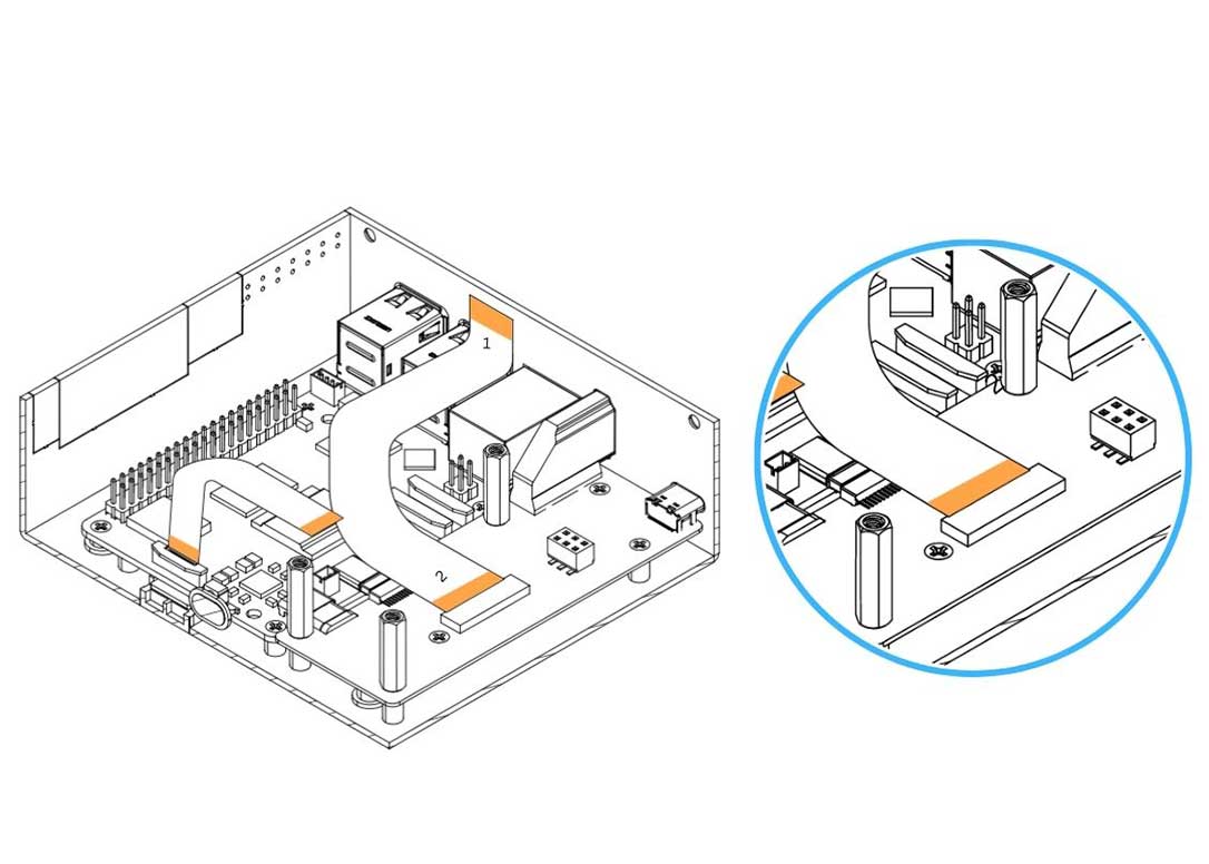
Step 5 — Connect the HMI-HDMI Flat Flex Cable to the Argon HMI-HDMI Board
Carefully connect the HMI-HDMI Flat Flex Cable to the connector on the Argon HMI-HDMI Board.
- Gently pull the flip-lock cover on the HDMI connector to release the lock.
- Insert the cable with the COPPER CONTACTS FACING the white side of the connector.
- Make sure to connect the no.2 end of the cable to this connector.
- Press the flip-lock back down firmly to secure the cable.
📝 Note: The HMI-HDMI Flat Flex Cable is directional — it has a labelled no.1 end and a no.2 end. The no.2 end connects to the HMI-HDMI Board (this step); the no.1 end connects to the Touch Display (Step 11). Reversing the ends will result in no display output.
Step 6 — Attach the Argon HMI NVMe Board
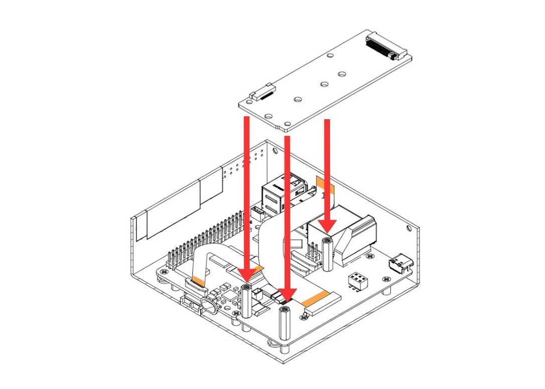
Carefully lower the Argon HMI NVMe Board on top of the Argon HMI-HDMI Board. Align the NVMe Board mounting holes to the standoffs installed in Step 4 and secure using the flat head screws.
Step 7 — Install the M.2 NVMe SSD and Secure the NVMe Board
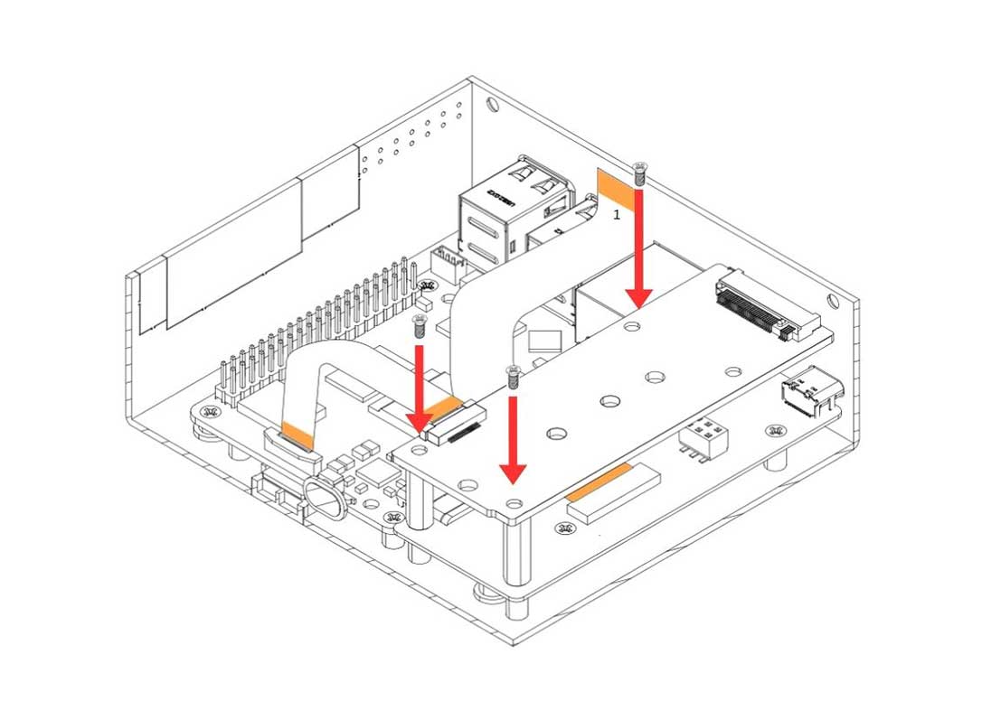
- Secure the Argon HMI NVMe Board to the standoffs using the flat head screws.
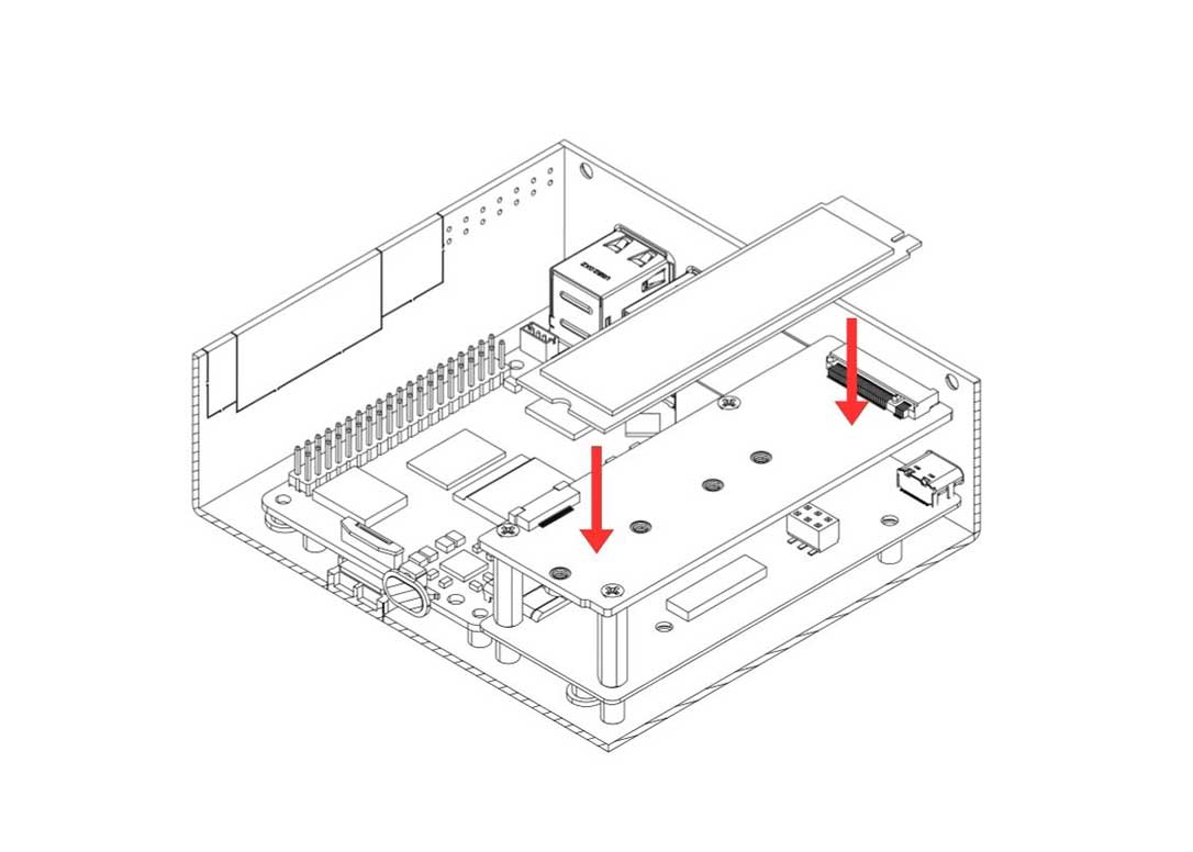
- Insert the M.2 NVMe SSD into the M.2 slot at an angle, press down flat, and secure using the NVMe screw.
📝 Note: Only PCIe NVMe M.2 drives in 2230 or 2242 form factors are supported. SATA M.2 drives will not function.
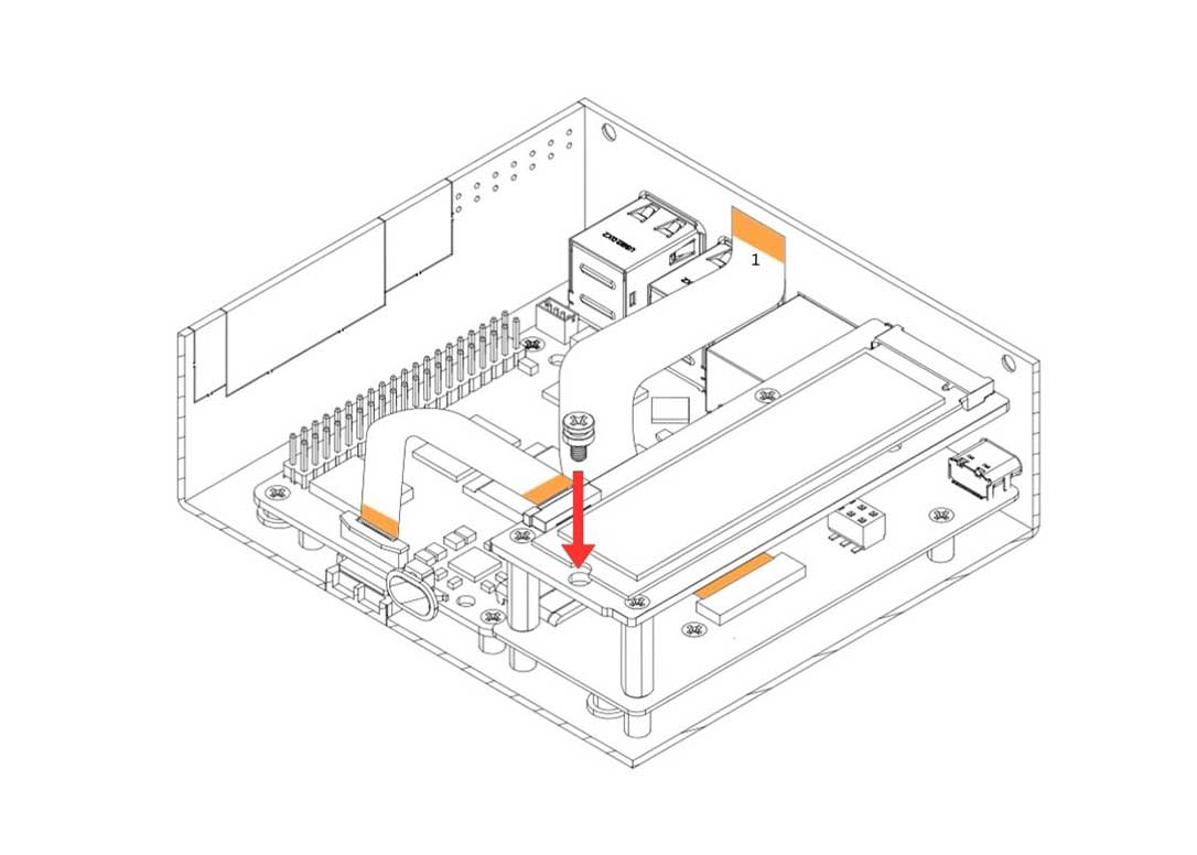
Step 8 — Connect the PCIe Flat Flex Cable to the Argon NVMe Board
Carefully connect the other end of the PCIe Flat Flex Cable (installed at the RPi 5 end in Step 3) to the PCIe connector on the Argon NVMe Board.
- Gently pull the flip-lock cover on the NVMe Board PCIe connector to release the lock.
- Insert the cable with the COPPER CONTACTS FACING the white side of the NVMe Board connector.
- Press the flip-lock back down firmly to secure the cable.
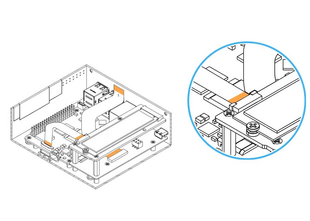
Step 9 — Attach the Passive Cooling Column and Bracket to the Display Case
- Attach the Passive Cooling Column to the Display Case and secure using the flat head screws.
- Attach the Display Case Bracket to the Display Case and secure using the flat head screws.
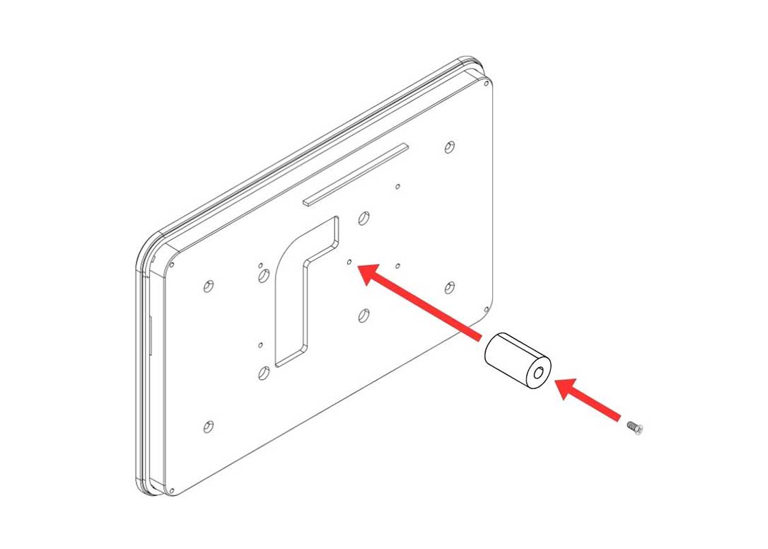
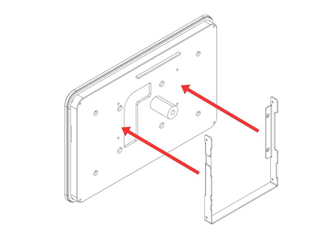
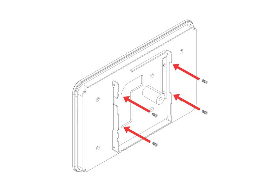
Step 10 — Attach the Argon 8" / 10" Touch Display to the Display Case
Place the Argon 8" / 10" Touch Display into the Display Case and secure using the flat head screws.
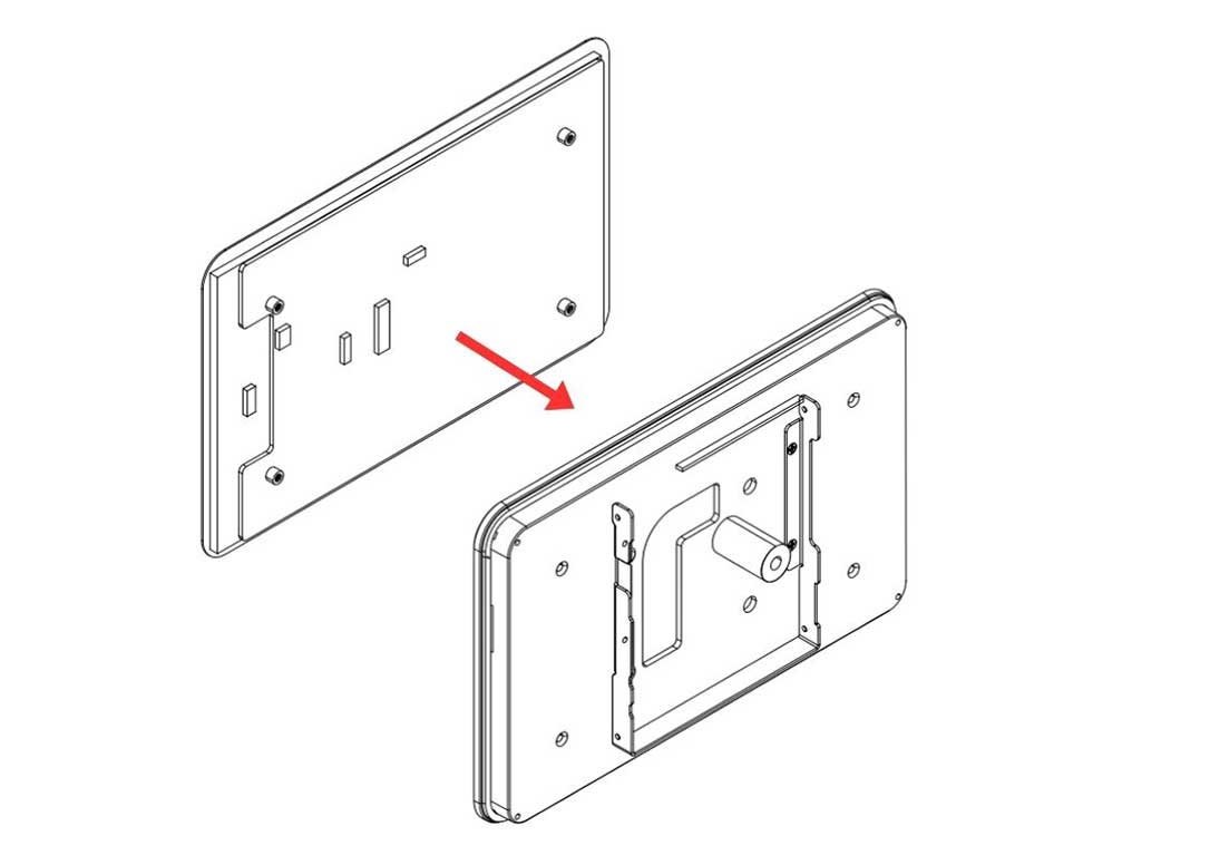
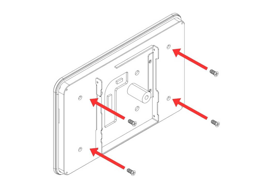
Step 11 — Connect the HMI-HDMI Flat Flex Cable to the Argon Touch Display
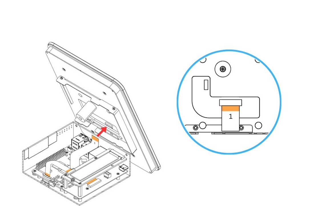
Carefully connect the HMI-HDMI Flat Flex Cable to the connector on the Argon Touch Display.
- Gently pull the flip-lock cover on the display connector to release the lock.
- Insert the cable with the COPPER CONTACTS FACING the white side of the Argon Touch Display connector.
- Make sure to connect the no.1 end of the cable to this connector.
- Press the flip-lock back down firmly to secure the cable.
⚠️ Warning: Ensure the no.1 end is connected to the display and the no.2 end is connected to the HMI-HDMI Board. Connecting the wrong ends will result in no display output.
Step 12 — Connect the Power Supply Cable to the GPIO
Carefully connect the 3-pin end of the Power Supply Cable to the Raspberry Pi 5 GPIO header. Ensure the cable is aligned to the correct pins:
| GPIO Pin | Function |
|---|---|
| Pin 2 | 5V Power |
| Pin 4 | 5V Power |
| Pin 6 | Ground (GND) |
⚠️ Warning: Connecting the power cable to the wrong GPIO pins can permanently damage the Raspberry Pi 5 or the Touch Display. Double-check pin alignment before powering on.
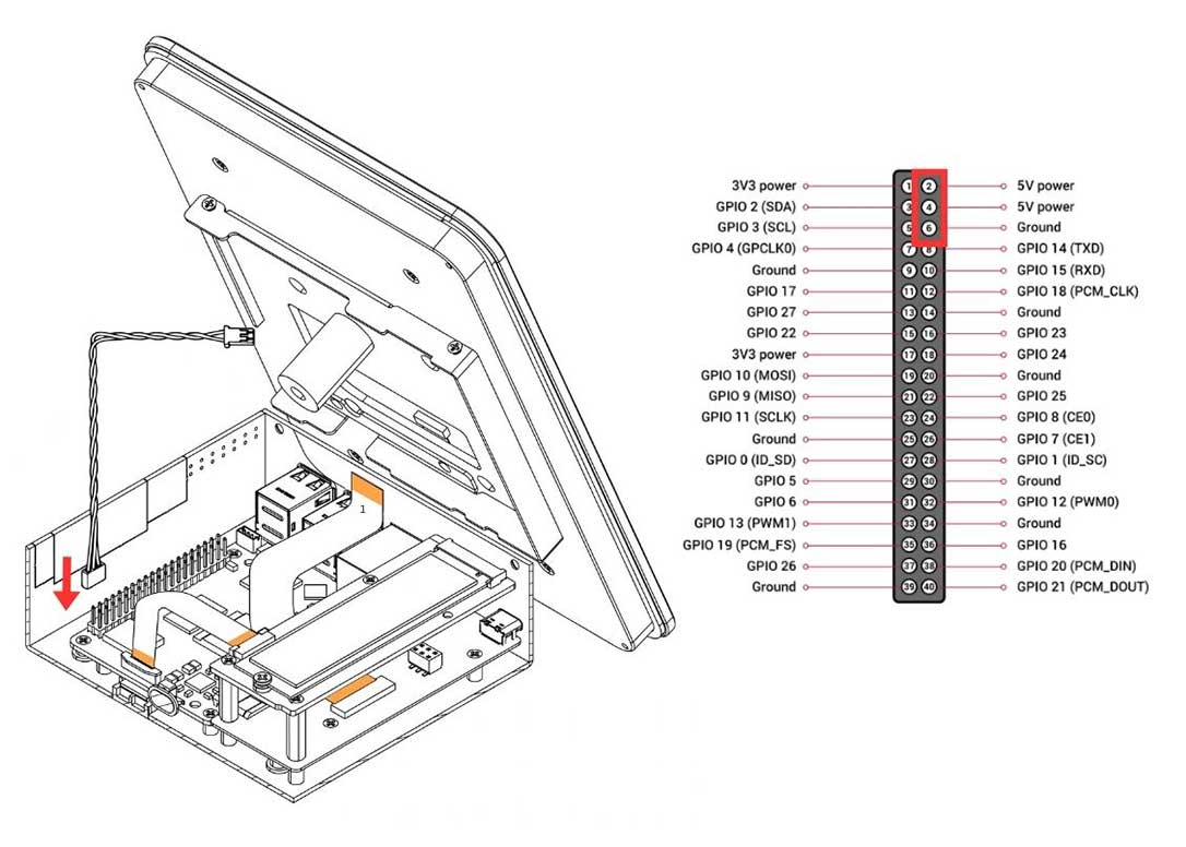
Step 13 — Connect the Power Supply Cable to the Argon Touch Display
Carefully connect the 2-pin end of the Power Supply Cable to the power connector on the Argon Touch Display. Make sure the connector is fully and correctly seated.
Step 14 — Attach the HMI Display Assembly to the Body
Carefully bring the Display Case assembly to the HMI Body and align the mounting points. Secure the Display Case to the Body using the silver flat head screws.
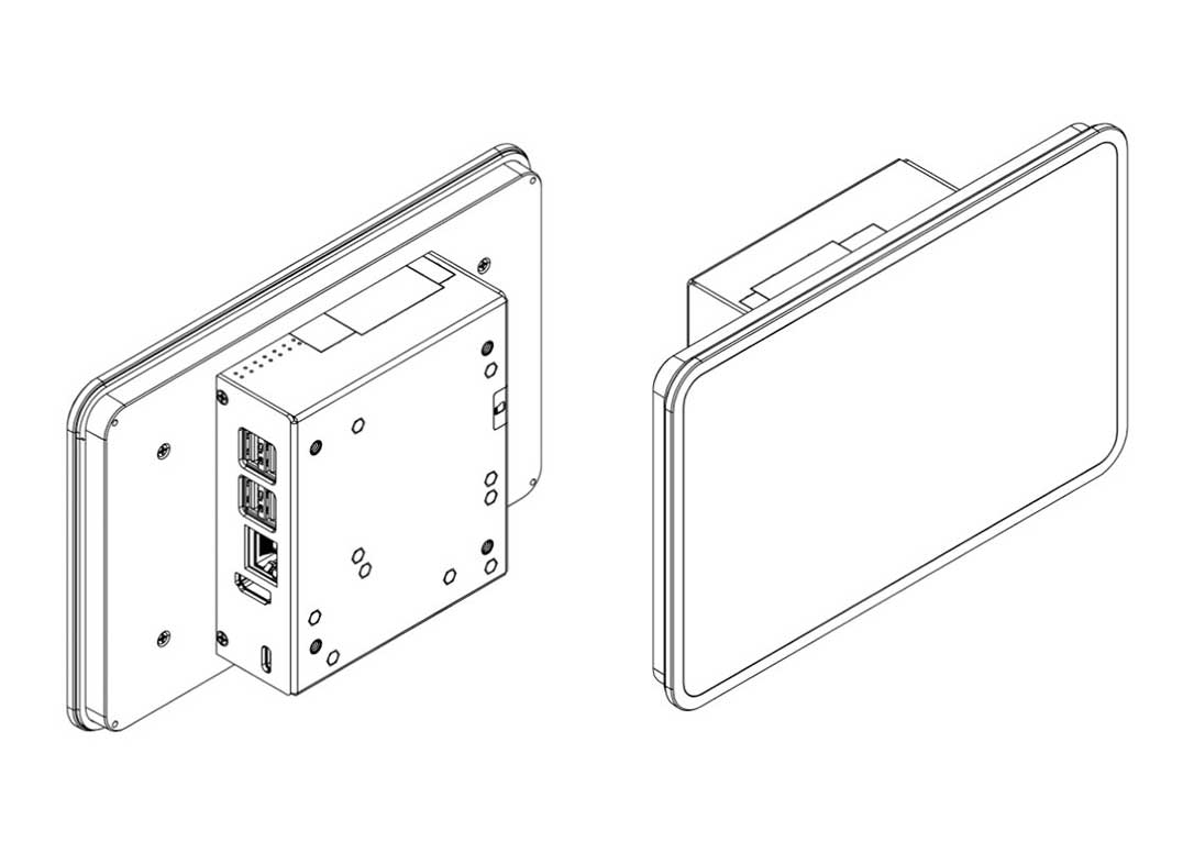
¶ Case Only Parts and Features
¶ Argon Industria HMI — Case Only

¶ Case Only Assembly & Setup
⚠️ Warning: Before beginning assembly, ensure the Raspberry Pi 5 is powered off and disconnected from any power source. Assembling under power may permanently damage the boards.
📝 Note: The 8" and 10" assembly uses an HMI-HDMI Flat Flex Cable to route the video signal to the display — this is a different cable routing method from the 5" / 7" SKUs. Pay close attention to the no.1 and no.2 end labelling on the cable at Steps 5 and 11.
Step 1 — Apply the Thermal Pad to the Raspberry Pi 5
Apply the Silicon Thermal Pad on the top of the Raspberry Pi 5 SoC. Make sure to REMOVE THE TRANSPARENT BACKING on both sides of the thermal pad before placing it. The pad must make direct contact with the SoC on one side and the passive cooling column on the other.
Step 2 — Connect the Raspberry Pi 5 to the Argon HMI-HDMI Board
Slide the Raspberry Pi 5 into the Argon HMI-HDMI Board connector. PUSH ALL THE WAY IN. The HDMI-Power Daughterboard must be FULLY SEATED into the RPi 5 GPIO and USB-C connectors to AVOID POWER-UP ISSUES.
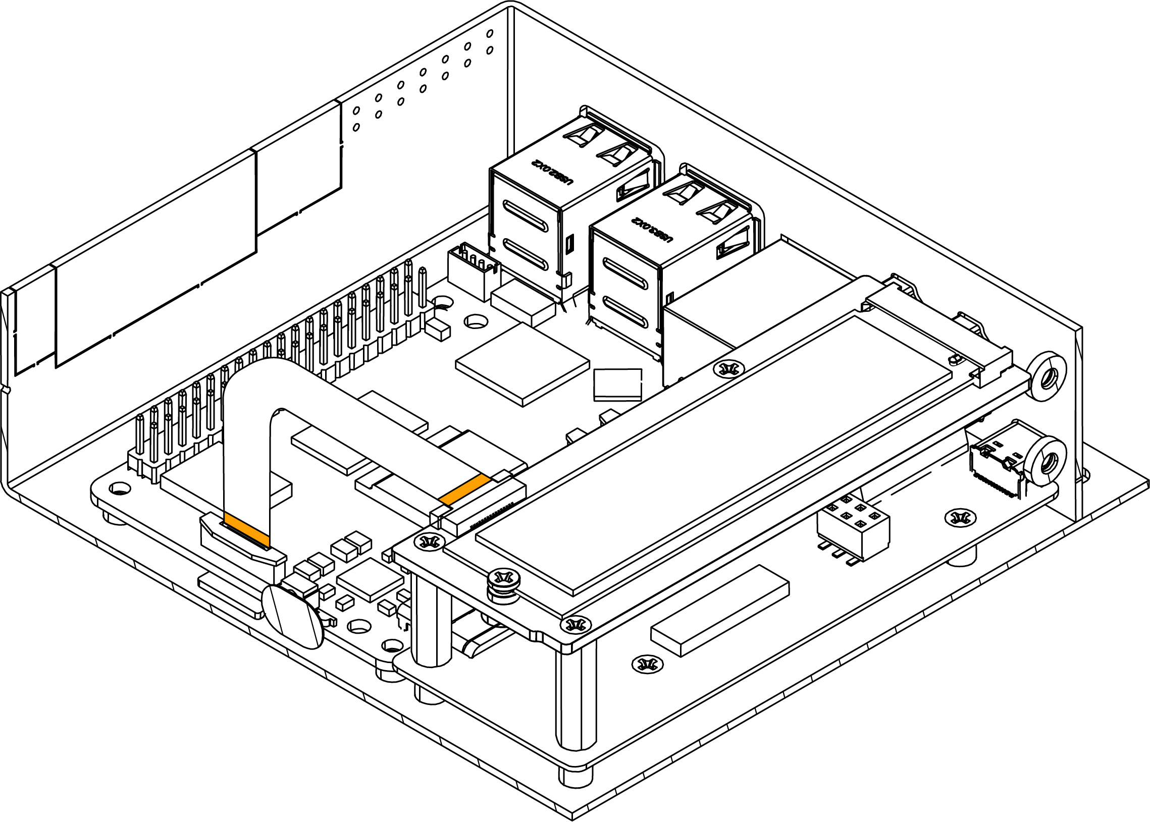
Step 3 — Connect the PCIe Flat Flex Cable to the Raspberry Pi 5
Carefully connect the PCIe Flat Flex Cable to the PCIe connector on the Raspberry Pi 5.
- Gently pull up the brown flip-lock cover on the RPi 5 PCIe connector to release the lock.
- Insert the cable with the COPPER CONTACTS FACING the white back side of the PCIe connector.
- Press the brown flip-lock back down firmly to secure the cable.
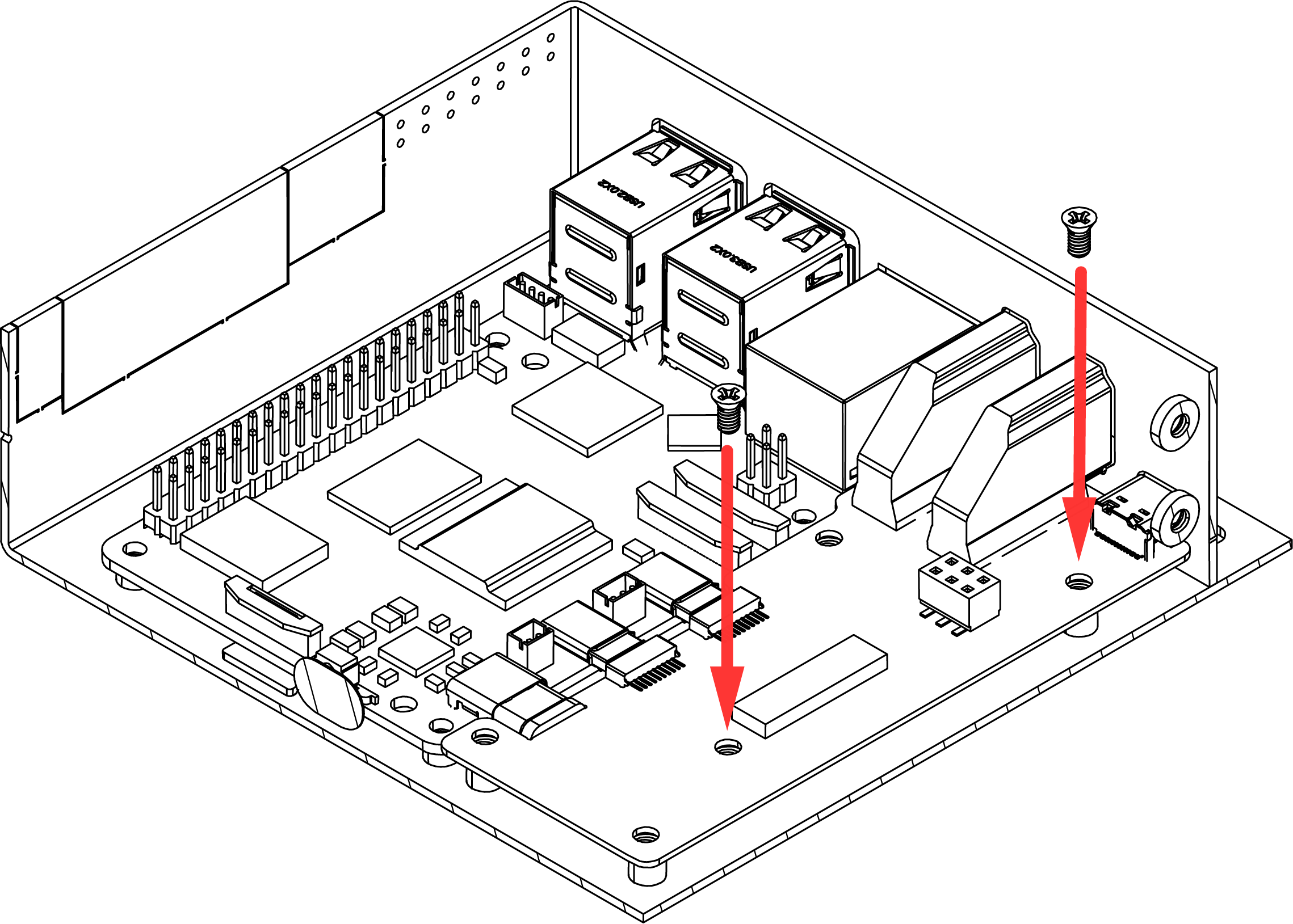
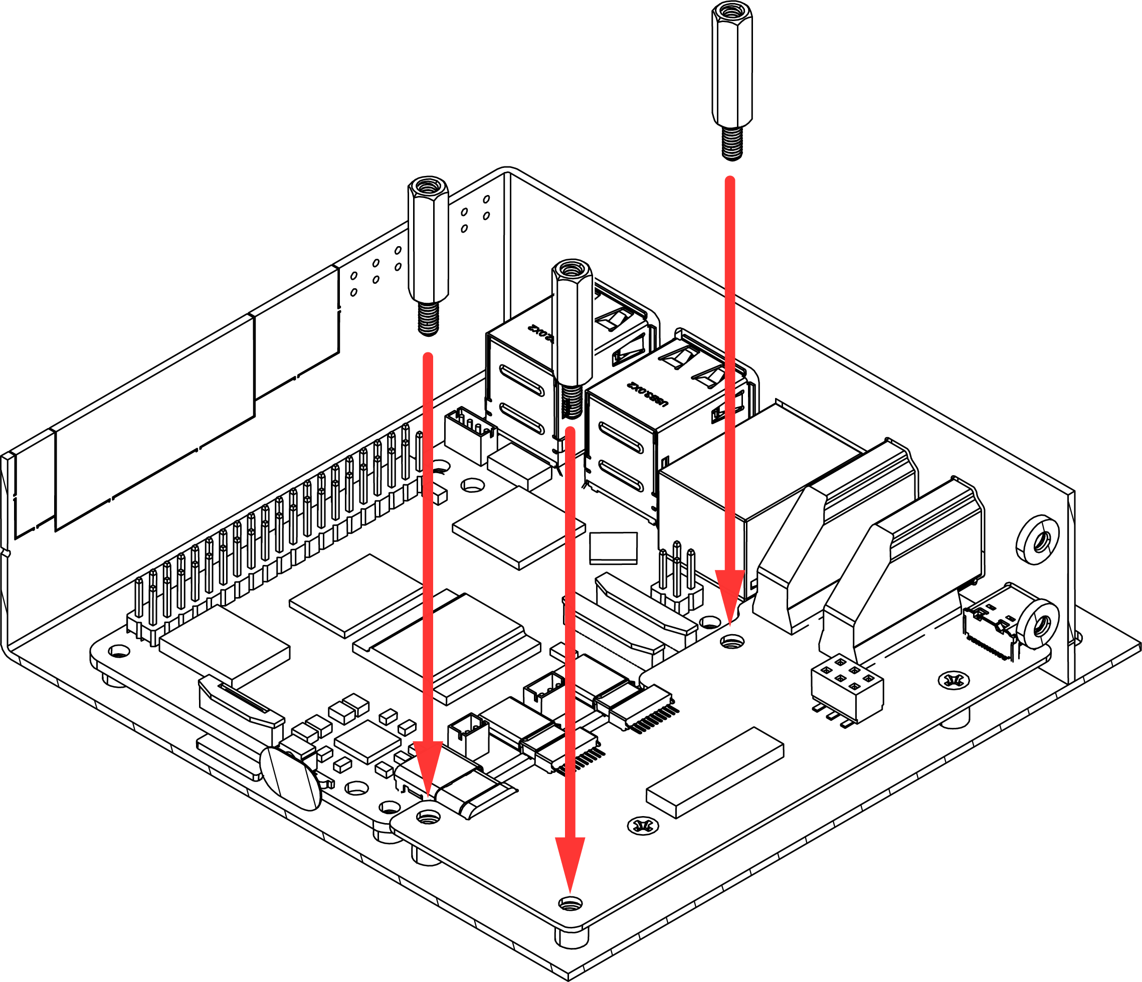
Step 4 — Mount the Boards into the Argon Industria HMI Case
Carefully lower the Raspberry Pi 5 and the Argon HMI-HDMI Board assembly into the Argon Industria HMI Body. Align the mounting holes and:
- Secure the Raspberry Pi 5 to the case using the flat head screws.
- Secure the Argon HMI-HDMI Board using the standoffs — these standoffs will also serve as the mounting points for the NVMe Board in the next step.
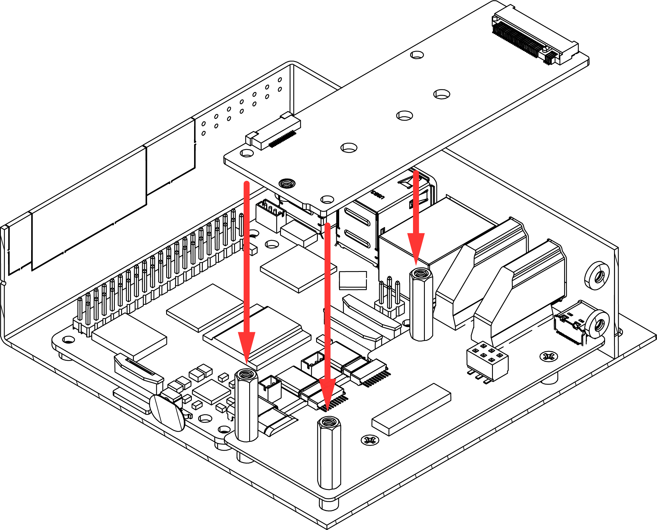
Step 5 — Attach the Argon HMI NVMe Board
Carefully lower the Argon HMI NVMe Board on top of the Argon HMI-HDMI Board. Align the NVMe Board mounting holes to the standoffs installed in Step 4 and secure using the flat head screws.

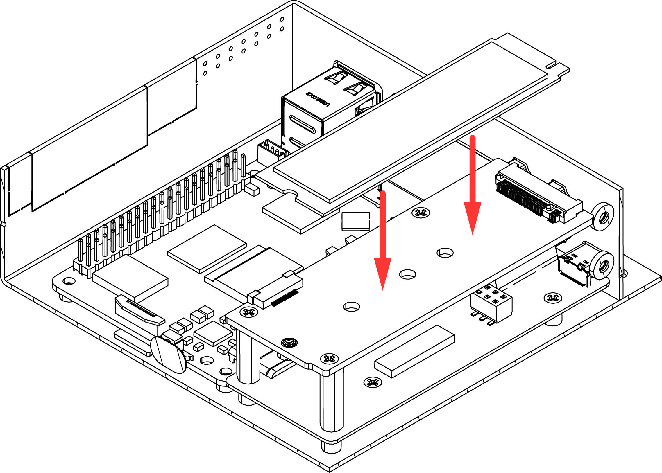
Step 6 — Install the M.2 NVMe SSD
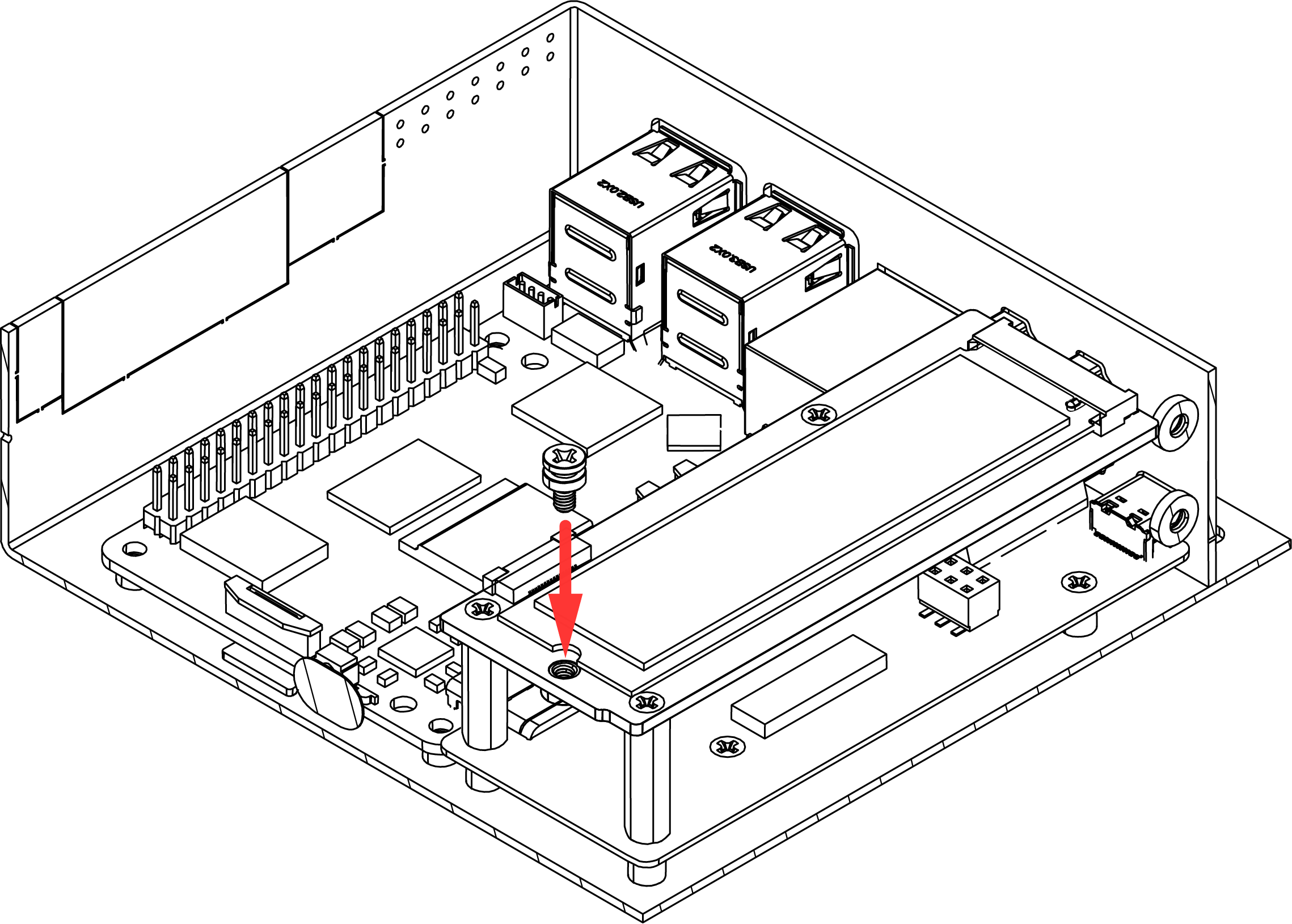
Insert the M.2 NVMe SSD into the M.2 slot on the Argon HMI NVMe Board at an angle, then press the drive down flat and secure it using the NVMe screw.
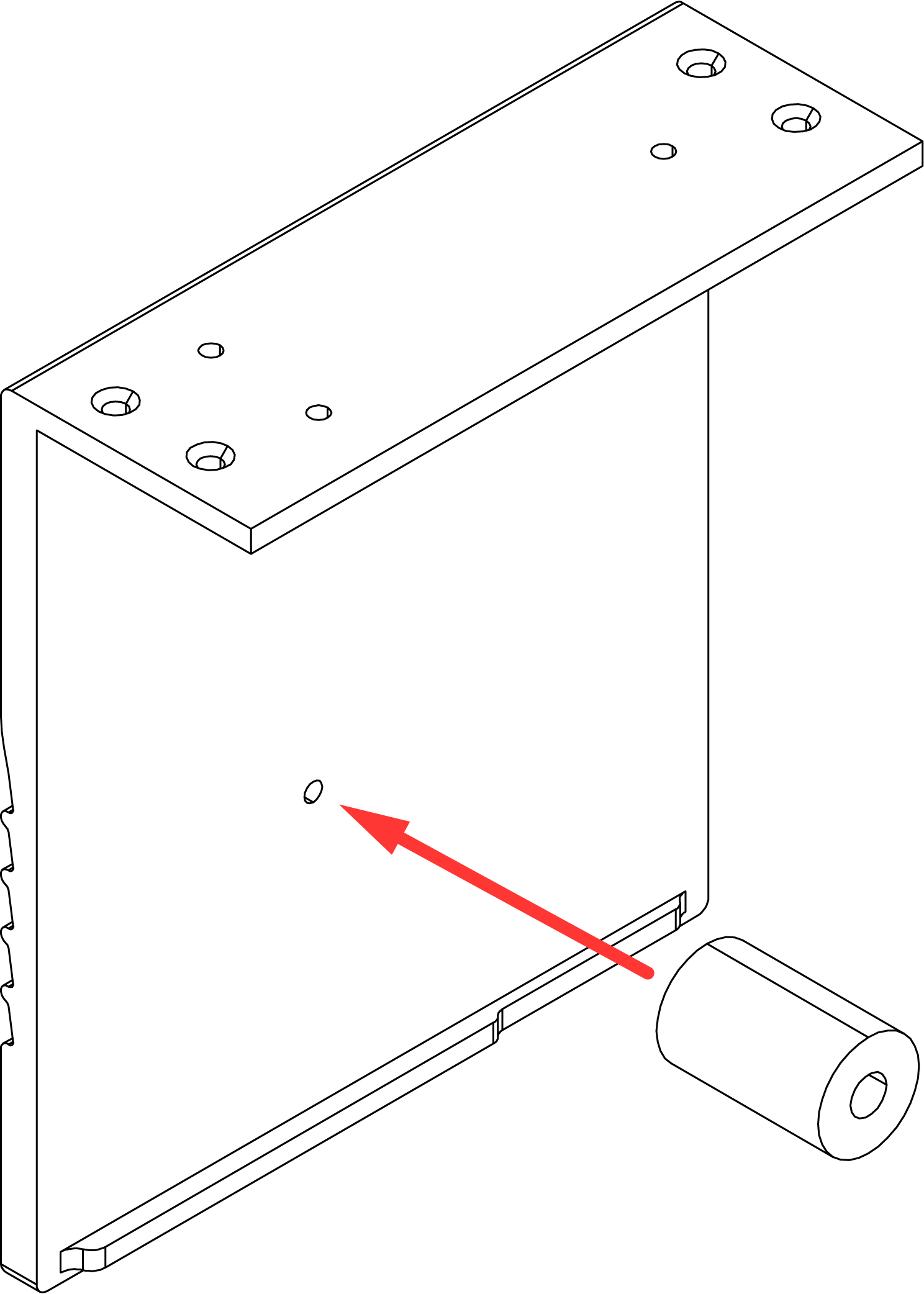
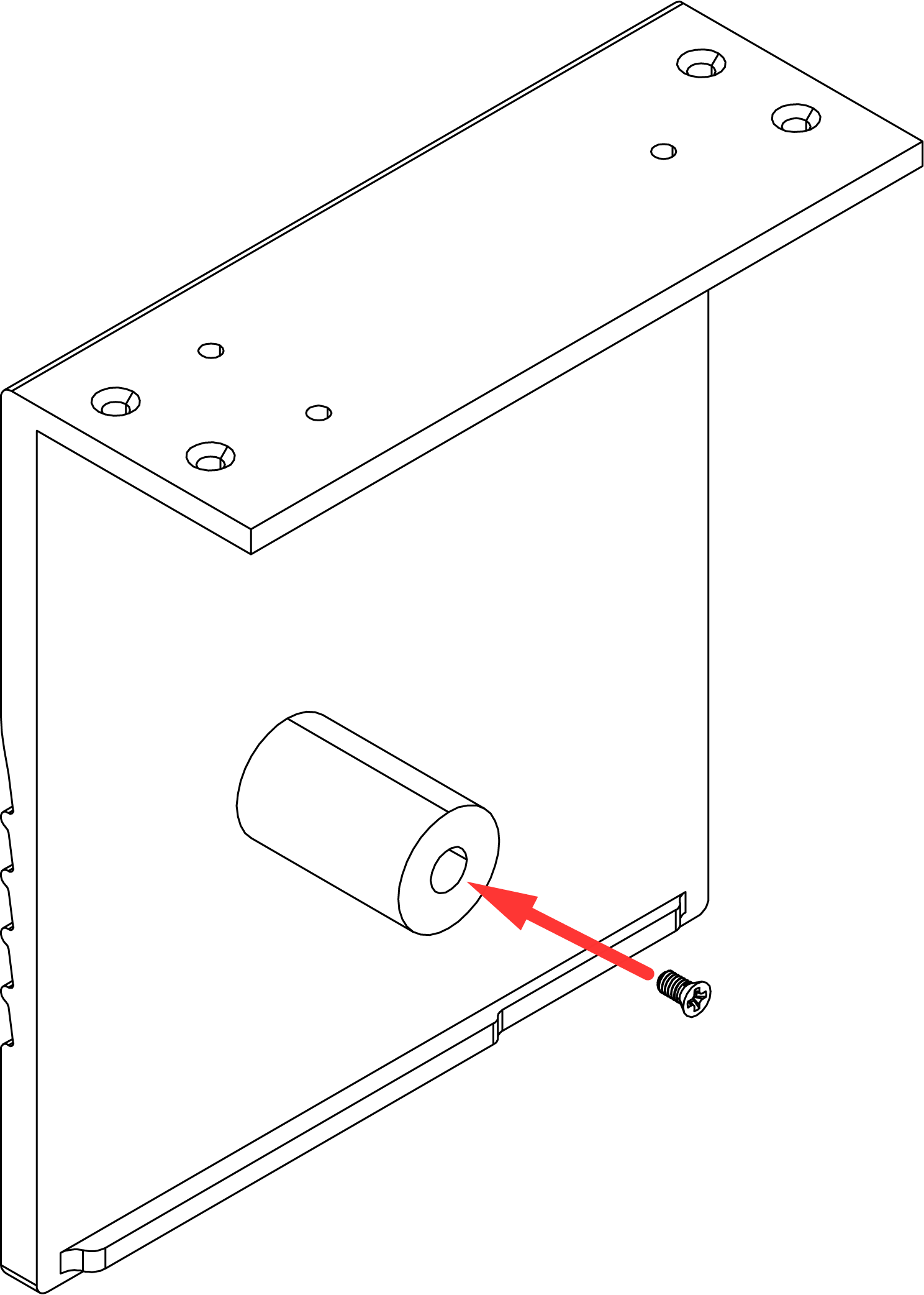
Step 7 — Attach the Passive Cooling Column to the Cover
- Attach the Passive Cooling Column to the Cover and secure using the flat head screws.
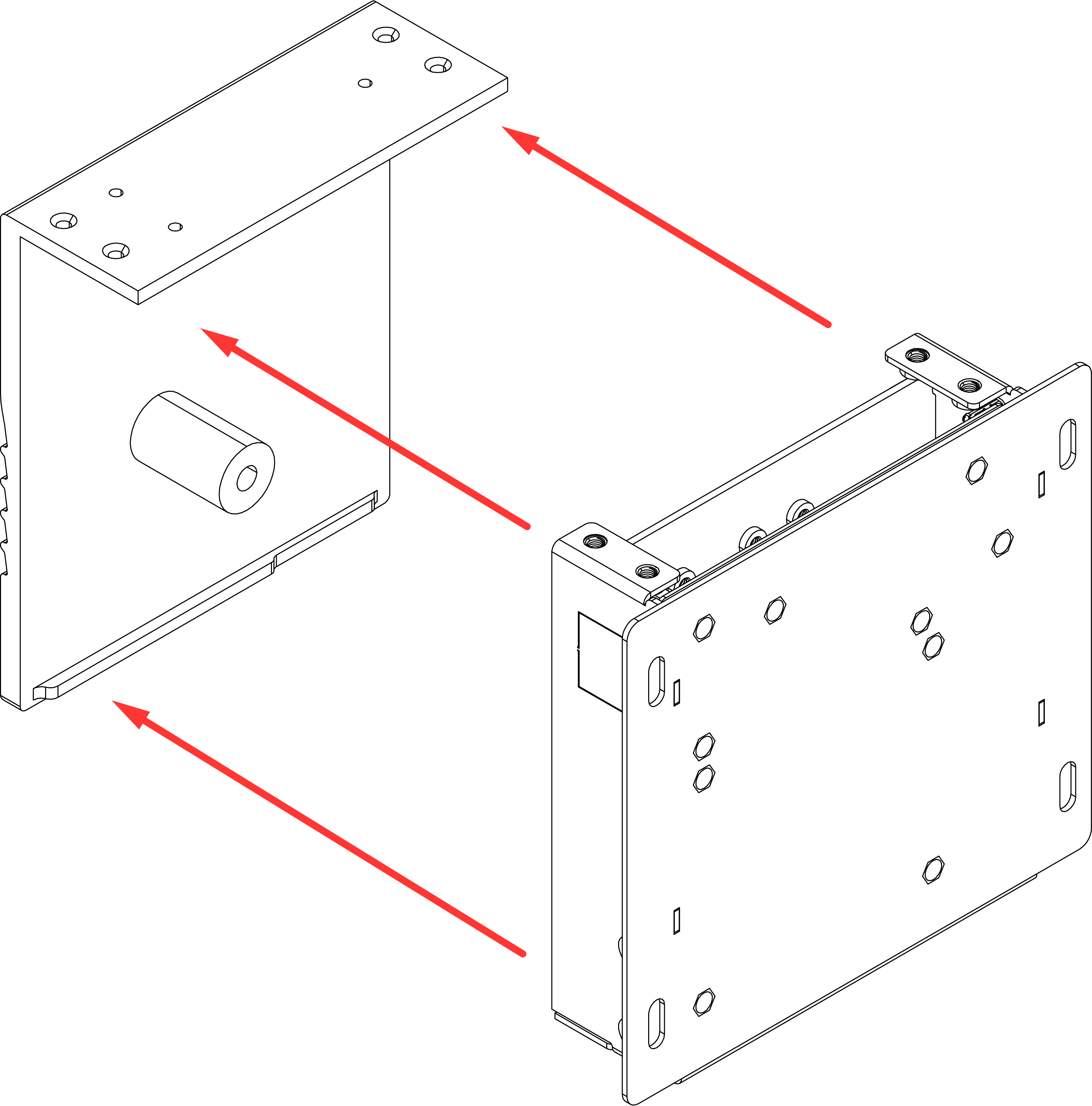
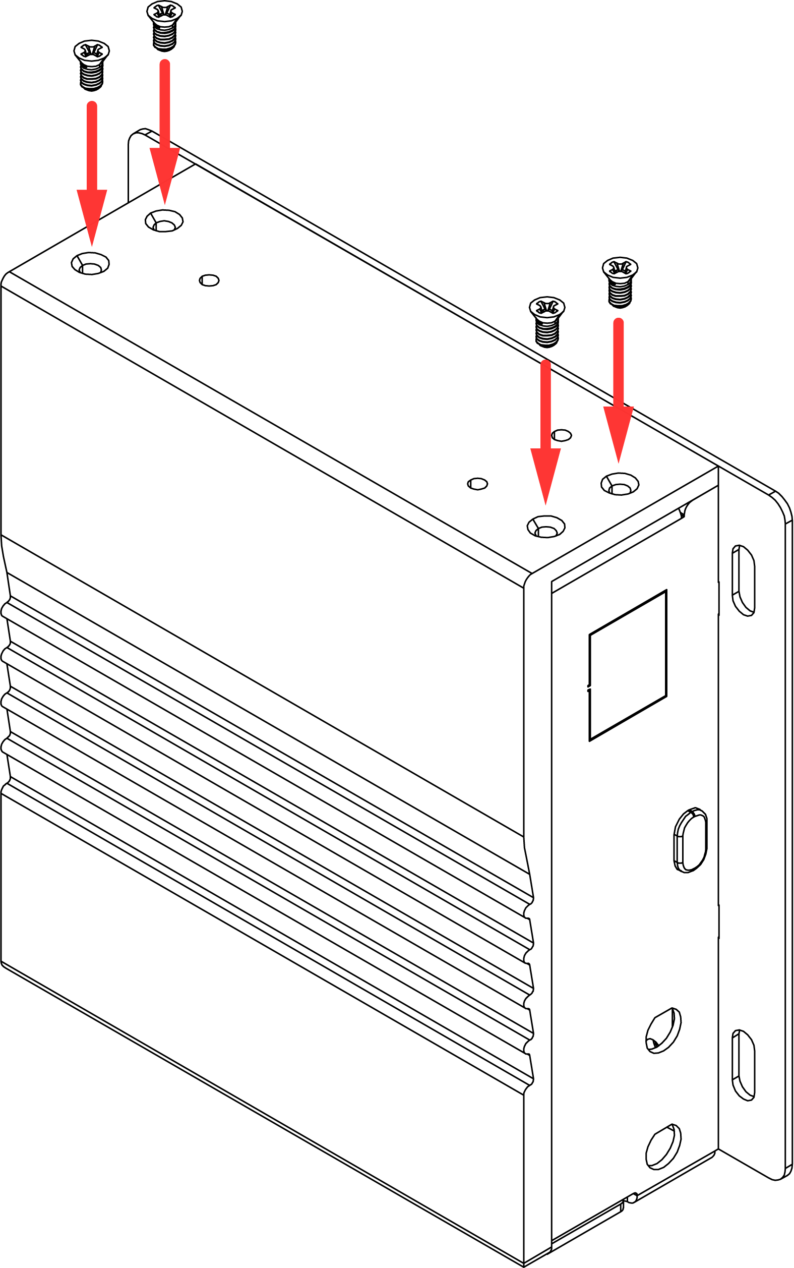
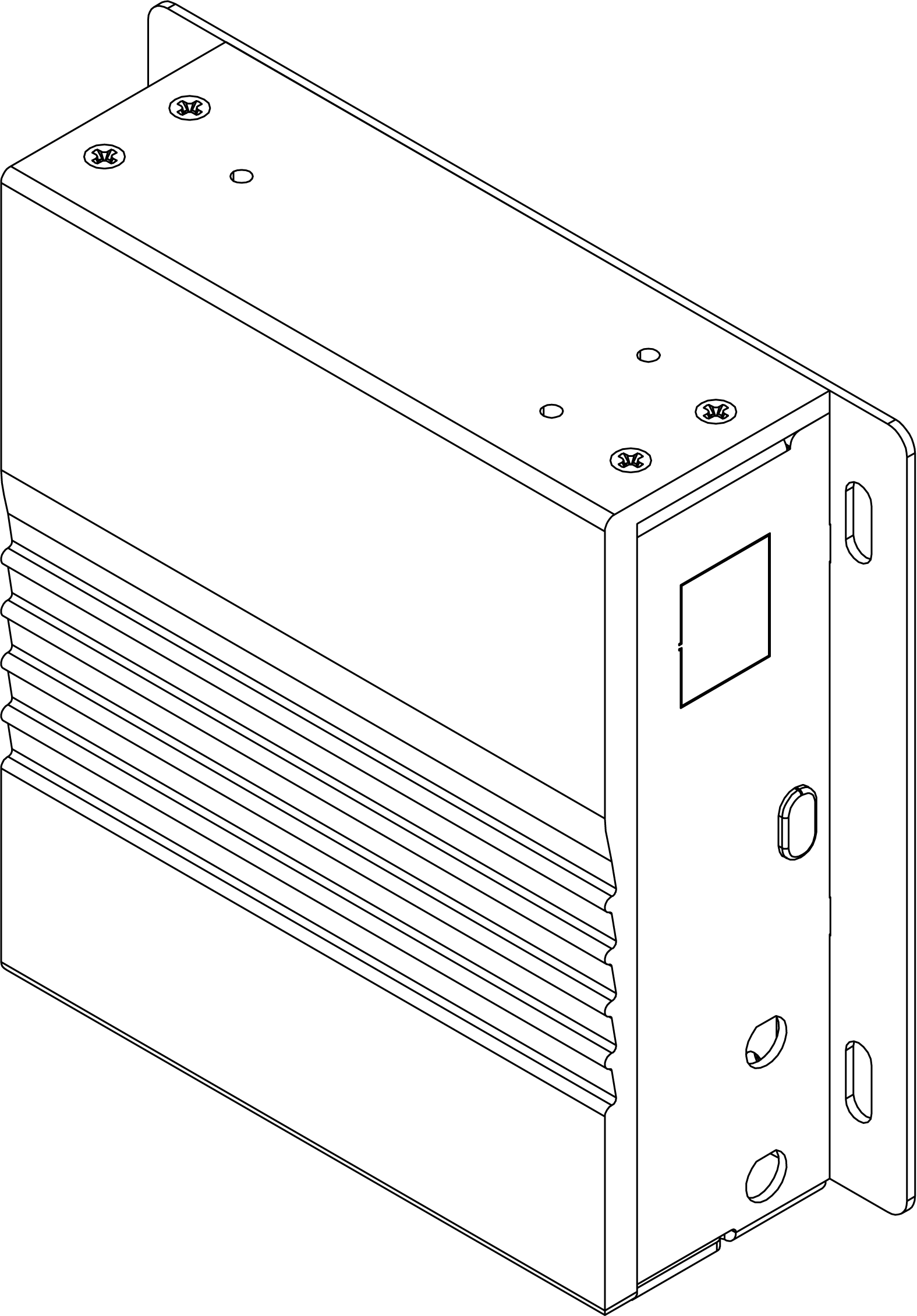
Step 8 — Attach the HMI Display Assembly to the Body
Carefully bring the Cover assembly to the HMI Body and align the mounting points. Secure the Cover to the Body using the silver flat head screws.
📋 Page Info
Revision: 1 · Published: 2026-07-15 06:49 UTC
Managed by Argon Wiki Tool · View live page